
 WhatsApp: +86 16626708626
 Email:
  Phone: +86 16626708626
Description
3. Key Technical Specifications
| Parameter | Value |
|---|---|
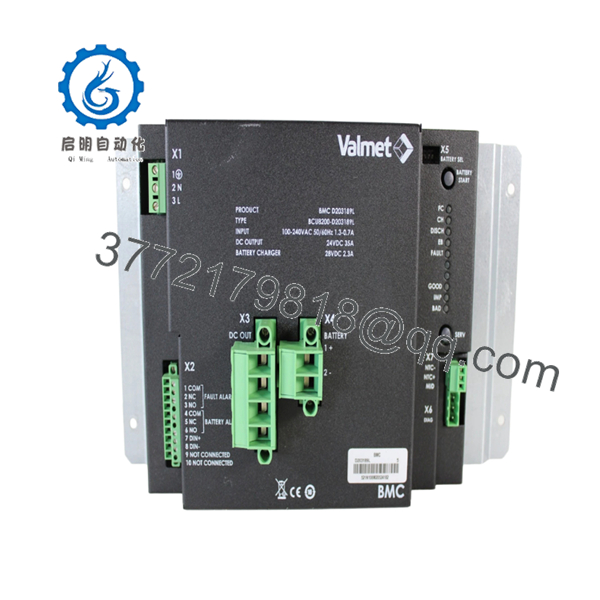
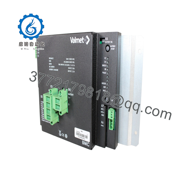
| Manufacturer | Valmet Automation |
| Model Number | BCU8200-D203189L |
| Product Type | Control Board Module |
| Hardware Category | Industrial Control PCB |
| Installation Method | Rack / Chassis Mounted |
| Primary Function | Control System Processing and Communication |
| Platform | BCU8200 Series |
| Application | Industrial Automation Systems |
| Typical Industries | Pulp & Paper, Marine, Process Industries |
| Availability Status | Obsolete / Surplus Market |
| Lifecycle Status | Discontinued Legacy Hardware |
| Replacement Requirement | Verify firmware and board revision compatibility |
4. Product Introduction
The VALMET BCU8200-D203189L is a control board module used within legacy Valmet automation architectures. Available market references identify the unit as a control PCB designed for industrial control systems and marine automation spare-part inventories.
In operating facilities that continue to support legacy Valmet hardware, the BCU8200-D203189L is typically procured as a direct replacement spare. Because OEM technical information is limited, engineers should verify board revision levels, firmware versions, connector arrangements, and system compatibility before installation.

- BCU8200-D203189L
- BCU8200-D203189L
5. Installation & Configuration Guide
Stage 1: Pre-Installation Preparation
Estimated Time: 10–15 Minutes
⚠️ Safety First
- Notify operations of the planned outage.
- Place the process in a safe condition.
- Apply Lock-Out/Tag-Out procedures.
- Remove all control power sources.
- Wait at least 5 minutes for capacitor discharge.
Tools Required
- ESD wrist strap
- PH1 screwdriver
- Fluke 115 multimeter
- Wire labels
- Smartphone camera
- Flashlight
Data Backup
- Export all controller configurations.
- Backup application logic.
- Record network settings and node addresses.
- Photograph:
- Module location
- DIP switches
- Jumper settings
- Connector assignments
- Wiring layouts
⚠️ Critical
Document every label on the existing board before removal.
I’ve seen technicians order the correct BCU board number but miss a revision suffix difference. The replacement physically fit, yet communications never initialized because the firmware generations differed.
Stage 2: Removing the Old Module
Estimated Time: 5–10 Minutes**
- Open cabinet doors and remove protective covers.
- Label all field and communication connections.
- Disconnect wiring carefully.
- Release retaining clips or mounting hardware.
- Pull the module straight outward.
Backplane Inspection
Inspect for:
- Bent connector pins
- Corrosion
- Oxidation
- Dust contamination
- Loose connectors
⚠️ Important
Retain the original module until the replacement has completed startup, communication verification, and at least one production cycle.
Stage 3: Installing the New Module
Estimated Time: 10 Minutes
Step 1 – ESD Protection
- Wear a grounded wrist strap.
- Use an ESD-safe work surface.
- Handle the PCB only by the edges.
Step 2 – Configuration Clone (CRUCIAL)
- Verify:
- Model number
- Hardware revision
- Firmware revision
- Board markings
- Duplicate:
- DIP switch settings
- Jumper positions
- Address settings
- Termination settings
❗ This is the most common rookie mistake, but it happens constantly. Take a picture before you pull it. I can’t stress this enough.
Step 3 – Install the Module
- Align guide rails carefully.
- Insert evenly.
- Fully seat the board.
- Verify locking hardware engages.
Step 4 – Reconnect Wiring
- Reconnect cables according to documentation.
- Verify shield grounding.
- Confirm all connectors are fully engaged.
Self-Checklist
- Model number verified
- Revision verified
- DIP switches match
- Wiring secure
- Module fully seated
- Locking hardware engaged
Stage 4: Power-On & Testing
Estimated Time: 15–20 Minutes
Pre-Power Checks
- Verify 24 V supply integrity.
- Check for shorts with a multimeter.
- Confirm ground continuity.
Power-Up Procedure
- Energize the rack only.
- Observe startup LEDs.
- Verify normal initialization.
- Connect engineering workstation.
- Verify module recognition.
- Confirm firmware version.
- Restore configuration if required.
- Verify communications.
- Perform I/O testing.
Functional Verification
- No active diagnostics
- Stable communications
- No watchdog alarms
- Normal process updates
- Correct I/O response
⚠️ Troubleshooting Note
- Solid fault LED → suspect firmware mismatch or hardware revision conflict.
- No communication → verify addressing, network parameters, and switch settings.
- Intermittent faults → inspect backplane connectors and grounding integrity.
6. Frequently Asked Questions (FAQ)
Q1. Can I hot-swap the VALMET BCU8200-D203189L?
No.
Unless your specific Valmet platform documentation explicitly supports online replacement, assume the BCU8200-D203189L is not hot-swappable. Removing a control board under power can generate communication faults and potentially damage the backplane.
Q2. Is the BCU8200-D203189L obsolete?
Yes.
The BCU8200-D203189L is generally found through surplus inventory channels and legacy automation suppliers rather than current OEM production programs. Available market references identify it as a legacy control board product.
Q3. Is this a CPU module or an I/O module?
Based on available references, it is most accurately classified as a control board module.
Unlike clearly documented CPU modules such as A413001 or communication modules such as A413075, publicly available information does not definitively classify the BCU8200-D203189L as either the primary processor or a dedicated I/O module. Verify the installed board function from site documentation before ordering.
Q4. What should I verify before purchasing?
Verify:
- BCU8200-D203189L part number
- Hardware revision
- Firmware revision
- Connector layout
- Rack compatibility
- Existing board markings
For legacy Valmet hardware, revision compatibility often matters as much as the base model number.
Q5. What is the most common replacement mistake?
Firmware revision mismatch.
I’ve personally seen engineers spend two full shifts troubleshooting communication alarms because the replacement board carried a newer firmware revision than the installed system expected.
Document the original firmware before placing an order.
Q6. Why are New Surplus units often expensive?
Because availability is limited.
Many BCU-series boards have been out of production for years. When a paper machine, boiler control system, or marine automation system depends on a specific board, the cost of downtime typically exceeds the cost of the spare module.
Q7. What quality-control process should be performed before shipment?
Inbound Inspection & Traceability
- OEM label verification
- Serial number recording
- Anti-counterfeit inspection
- Visual examination for:
- Corrosion
- Scratches
- Rework marks
- UV yellowing
Live Functional Testing
- Installation in a compatible Valmet test rack
- Power-on verification
- Communication handshake testing
- I/O simulation where applicable
- Continuous operation for at least 24 hours
- Formal test report generation
Electrical Parameter Testing
- 500 V Megger insulation resistance test (>10 MΩ)
- Ground continuity verification
- Hipot testing where applicable
Firmware & Configuration Verification
- Record firmware version
- Record hardware revision
- Photograph DIP switches
- Photograph jumper settings
Final QC & Packaging
- QC inspector sign-off
- Anti-static ESD packaging
- Bubble-wrap protection
- Heavy-duty corrugated carton
- QC Passed label with inspection date
Test photos and startup videos should be available upon request.
Common Replacement Pitfalls
❗ Firmware Revision Mismatch
I’ve seen a replacement board initialize correctly but fail network communication because the firmware generation differed from the rest of the installed system.
Always document the existing firmware before ordering.
❗ DIP Switch Misconfiguration
Factory defaults rarely match plant settings.
Take photographs before removal and duplicate every switch position.
❗ Connector and Pinout Assumptions
Even within the same Valmet family, board revisions can introduce connector changes.
Always verify against drawings rather than wiring from memory.
❗ Power Supply Capacity
Verify rack power consumption and maintain at least a 20% reserve margin.
Aging power supplies often become marginal long before they completely fail.
❗ Electrostatic Discharge (ESD)
I once watched an engineer remove a legacy processor board during winter maintenance without an ESD strap. The board failed immediately after power-up.
Use a grounded wrist strap and ESD-safe work surface every time.
Keep these checks in mind and you’ll save yourself 90% of typical rework time.


