
 WhatsApp: +86 16626708626
 Email:
  Phone: +86 16626708626
Description
3. Key Technical Specifications
| Parameter | Value |
|---|---|
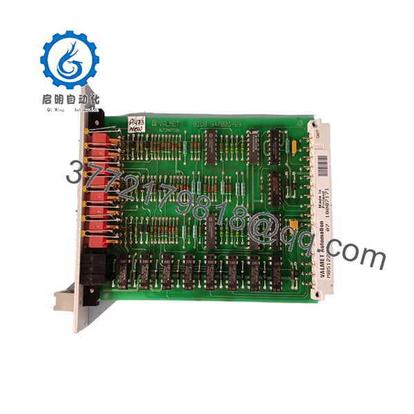
| Manufacturer | Valmet Automation |
| Model Number | M851222 |
| Product Type | Control Board Module |
| Hardware Category | Industrial Control PCB |
| Installation Method | Rack / Chassis Mounted |
| Application | Industrial Automation Systems |
| System Role | Control and Signal Processing |
| Platform Compatibility | Legacy Valmet Systems |
| Board Construction | Multi-layer Industrial PCB |
| Lifecycle Status | Obsolete |
| Availability | New Surplus / Refurbished Market |
| Verification Requirement | Confirm Revision Before Purchase |
4. Product Introduction
The VALMET M851222 is a control board module used within legacy Valmet automation systems. The module functions as part of the control architecture responsible for signal processing, system communications, and automation control tasks depending on the installed application.
In field support situations involving older pulp and paper mills, power generation facilities, and process plants, modules such as the M851222 are commonly sourced from surplus inventory to maintain existing systems while avoiding the cost and downtime associated with a complete control system migration. Hardware revision and firmware compatibility should always be verified before installation.

- M851222
- M851222
5. Installation & Configuration Guide
Stage 1: Pre-Installation Preparation
Estimated Time: 10–15 Minutes
⚠️ Safety First
- Notify operations of planned downtime.
- Place the process in a safe operating condition.
- Apply Lock-Out/Tag-Out procedures.
- Remove all control power sources.
- Wait at least 5 minutes for capacitor discharge.
Tools Required
- ESD wrist strap
- PH1 screwdriver
- Fluke 115 multimeter
- Wire labels
- Smartphone camera
- Flashlight
Data Backup
- Export controller configuration files.
- Backup application programs.
- Record all network settings.
- Photograph:
- Rack location
- Wiring layout
- Connector positions
- DIP switches
- Jumper settings
- Board labels
⚠️ Critical Action
Record every identification label on the existing board before removal.
I’ve seen maintenance teams order the correct board number but receive a different hardware revision. The replacement powered up normally but failed communication checks because the firmware generation did not match the installed system.
Stage 2: Removing the Old Module
Estimated Time: 5–10 Minutes
- Open cabinet doors.
- Remove protective covers.
- Label all wiring and connectors.
- Disconnect cables carefully.
- Release retaining hardware.
- Pull the board straight out.
Backplane Inspection
Check for:
- Bent pins
- Connector wear
- Dust accumulation
- Corrosion
- Oxidation
⚠️ Important
Keep the original board available until the replacement has successfully completed startup and process verification.
Stage 3: Installing the New Module
Estimated Time: 10 Minutes
Step 1 – ESD Protection
- Wear a grounded wrist strap.
- Use an ESD-safe work surface.
- Handle the board only by its edges.
Step 2 – Configuration Clone (CRUCIAL)
- Verify:
- M851222 model number
- Hardware revision
- Firmware labels
- Board assembly markings
- Replicate:
- DIP switch settings
- Jumper positions
- Address settings
- Termination settings where applicable
❗ This is the most common rookie mistake, but it happens constantly. Take a picture before you pull it. I can’t stress this enough.
Step 3 – Install Module
- Align guide rails.
- Insert evenly.
- Seat fully into the backplane connector.
- Verify retaining clips engage properly.
Step 4 – Reconnect Wiring
- Reconnect all connectors.
- Verify shield grounding.
- Confirm cable routing matches original installation.
Self-Checklist
- Model number verified
- Revision verified
- DIP switches match
- Wiring secure
- Board fully seated
- Locking hardware engaged
Stage 4: Power-On & Testing
Estimated Time: 15–20 Minutes
Pre-Power Checks
- Verify supply voltage.
- Check for shorts using a multimeter.
- Confirm ground continuity.
Power-Up Procedure
- Energize the rack only.
- Observe status indicators.
- Verify normal startup sequence.
- Connect engineering workstation.
- Confirm module recognition.
- Verify communication status.
- Restore configuration if required.
- Perform functional testing.
Functional Verification
- No active diagnostics
- Stable communications
- No watchdog alarms
- Normal I/O response
- Correct process operation
⚠️ Troubleshooting Note
- Fault indication after startup → verify firmware and revision compatibility.
- No communications → check addressing and network parameters.
- Intermittent operation → inspect backplane connectors and grounding.
6. Frequently Asked Questions (FAQ)
Q1. Is the VALMET M851222 still in production?
No.
The M851222 belongs to a legacy generation of Valmet automation hardware. Current availability is generally limited to surplus inventory, plant spare stock, and specialized industrial automation suppliers.
Q2. Can I hot-swap the M851222?
No.
Unless your specific Valmet platform documentation explicitly supports online replacement, power down the rack before removing the module.
Removing control boards under power can create backplane faults and communication failures.
Q3. What should I verify before ordering?
Verify all of the following:
- M851222 model number
- Hardware revision
- Firmware EPROM labels
- Connector layout
- Rack location
- Daughterboard assemblies
For legacy Valmet hardware, matching the part number alone is often not enough.
Q4. Will my existing configuration transfer automatically?
Not necessarily.
Some legacy systems store configuration data externally, while others rely on local board settings, EPROMs, or controller memory.
Always create backups before replacement.
Q5. What is the most common installation problem?
Firmware revision mismatch.
I’ve personally seen replacement boards pass startup diagnostics but fail communication with neighboring modules because the firmware versions were different.
Always document firmware labels before ordering.
Q6. Why do prices vary significantly between suppliers?
Several factors influence pricing:
- New Surplus versus Refurbished condition
- Availability of test reports
- Traceability documentation
- Warranty coverage
- Inventory scarcity
For obsolete hardware, documented functional testing is usually more important than cosmetic appearance.
Q7. What quality-control process should a supplier perform before shipment?
Inbound Inspection & Traceability
- Verify OEM labels.
- Record serial numbers.
- Conduct anti-counterfeit checks.
- Inspect for:
- Corrosion
- Scratches
- Rework marks
- UV yellowing
Live Functional Testing
- Install in a compatible Valmet test rack.
- Verify startup sequence.
- Test communications.
- Simulate I/O signals where applicable.
- Perform continuous operation for at least 24 hours.
- Generate a formal test report.
Electrical Parameter Testing
- 500 V Megger insulation resistance test (>10 MΩ)
- Ground continuity verification
- Hipot testing where applicable
Firmware & Configuration Verification
- Record firmware versions.
- Record hardware revisions.
- Photograph DIP switches.
- Document jumper settings.
Final QC & Packaging
- QC inspector approval.
- Anti-static ESD packaging.
- Bubble-wrap protection.
- Heavy-duty corrugated carton.
- QC Passed label with inspection date.
Test photos and startup videos should be available upon request.
Common Replacement Pitfalls
❗ Firmware Revision Mismatch
I’ve seen a replacement board cause communication timeouts for nearly two days because the firmware generation differed from the installed system.
Document the original firmware before ordering.
❗ DIP Switch Misconfiguration
Factory defaults almost never match plant settings.
Take clear photos before removal and duplicate every setting.
❗ Connector Compatibility Assumptions
Never assume connector assignments remain identical between hardware revisions.
Always verify using system drawings.
❗ Power Supply Loading
Calculate total rack power consumption and maintain at least a 20% reserve margin.
Aging power supplies often create intermittent faults that look like board failures.
❗ Electrostatic Discharge (ESD)
I once watched an engineer unpack a replacement control board during a winter outage without using an ESD strap. The module failed immediately after startup.
Use a grounded wrist strap and ESD-safe work surface every time.


