
 WhatsApp: +86 16626708626
 Email:
  Phone: +86 16626708626
Description
Key Technical Specifications
| Parameter | Value |
|---|---|
| Manufacturer | Meggitt Sensing Systems / Vibro-Meter |
| Product Series | IPC704 |
| Part Number | 244-704-000-042-A2-B01-C10-D20-E2-F10000-C0-H0-I0 |
| Base Model | IPC704 Signal Conditioner |
| Signal Input | Piezoelectric charge signal |
| Environment Version | A2 – Explosive atmosphere Ex i version |
| Transfer Unit | B01 – pC/g to μA/g conversion |
| Input Sensitivity | C10 – 10.00 pC/g |
| Output Sensitivity | D20 – 20.00 μA/g |
| High-Pass Filter | E2 – 2 Hz |
| Low-Pass Filter | F10000 – 10,000 Hz |
| Installation | G0 – Signal conditioner only |
| Cable Fitting Input | H0 |
| Cable Fitting Output | I0 |
| Power Supply | 18 to 30 VDC |
| Maximum Current Consumption | 25 mA |
| Operating Temperature | −30 to +85 °C |
| Storage Temperature | −40 to +85 °C |
| Protection Rating | IP40 |
| Frequency Range | 0.5 Hz to 20 kHz |
The IPC704 converts the charge output from piezoelectric sensors into standardized current or voltage signals for transmission to monitoring systems. It supports configurable filtering and optional integration functions for vibration measurement applications.
Product Introduction
The Meggitt Vibro-Meter IPC704 244-704-000-042-A2-B01-C10-D20-E2-F10000-C0-H0-I0 is a piezoelectric sensor signal conditioner designed for vibration monitoring applications. It converts charge-based accelerometer signals into industrial transmission signals used by machinery protection and condition monitoring systems.
This specific configuration includes an Ex i hazardous-area version, 10.00 pC/g input sensitivity, 20 μA/g output sensitivity, and 2 Hz to 10 kHz filtering. It is typically installed with rotating machinery monitoring systems for compressors, pumps, turbines, and other critical assets.
Installation & Configuration Guide
Estimated replacement time: 20–45 minutes for an experienced instrumentation technician.
Stage 1: Pre-Installation Preparation
⚠️ Safety First
- Notify operations before removing the vibration monitoring device.
- Confirm the monitored machine is in a safe maintenance condition.
- Apply lockout/tagout before disconnecting field wiring.
- Verify hazardous-area requirements before opening or replacing equipment.
- Confirm the replacement unit matches the required Ex i configuration.
Tools Required
- ESD wrist strap
- PH1 screwdriver
- Digital multimeter
- Wire labels
- Smartphone/camera
- Loop calibrator (recommended)
- Meggitt/Vibro-Meter documentation
Data Backup
Before removal:
- Record the complete part number:
- 244-704-000-042-A2-B01-C10-D20-E2-F10000-C0-H0-I0
- Photograph the existing unit label.
- Record:
- Sensor model
- Cable routing
- Terminal assignments
- Output loop wiring
- Hazardous-area barrier arrangement
- Verify the existing input sensitivity and filter settings.
⚠️ Replacing an IPC704 with the wrong configuration can create incorrect vibration readings even if the unit powers on normally.
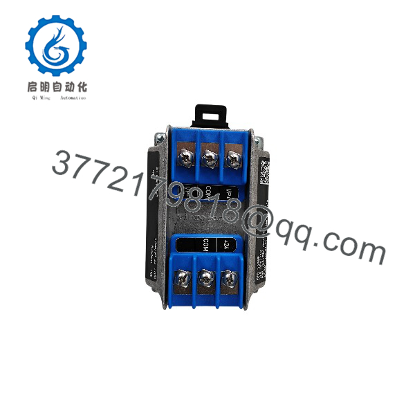
IPC704 244-704-000-042
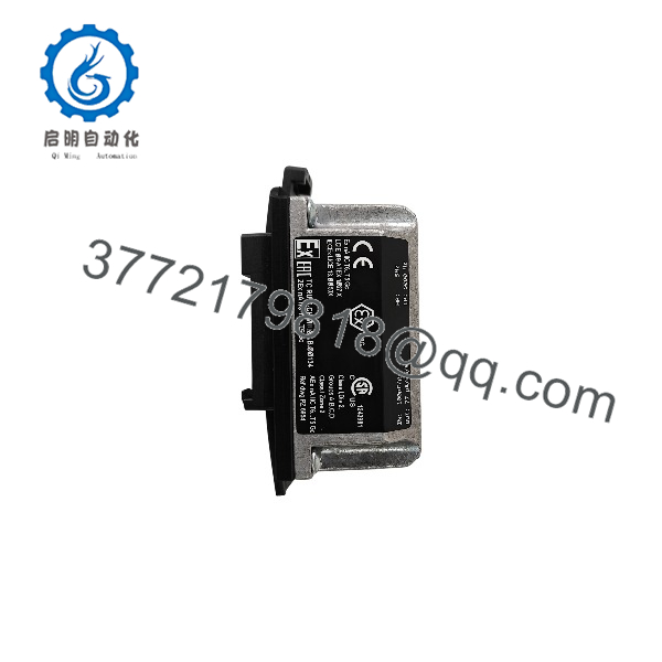
IPC704 244-704-000-042
Stage 2: Removing the Old Module
- Verify the loop power is isolated.
- Confirm the sensor circuit is safe to disconnect.
- Photograph all wiring before removal.
- Label input and output terminals.
- Disconnect sensor wiring carefully.
- Disconnect output signal wiring.
- Remove mounting hardware if installed.
- Inspect:
- Terminal condition
- Cable insulation
- Grounding/shielding
- Moisture contamination
⚠️ Keep the original signal conditioner until the replacement measurement has been verified.
Stage 3: Installing the New Module
- Wear ESD protection.
- Verify the complete IPC704 ordering code.
- Confirm:
- Ex i approval requirement
- Input sensitivity
- Output sensitivity
- Filter settings
- Mount the signal conditioner according to the installation requirements.
- Connect the piezo sensor input wiring.
- Connect the output transmission wiring.
- Verify polarity and shield termination.
- Confirm the 24 VDC supply is within specification.
Self-Checklist
- Correct configuration verified
- Ex i version confirmed
- Sensor sensitivity matched
- Wiring polarity checked
- Shielding restored
- Mounting secure
Stage 4: Power-On & Testing
- Restore loop power.
- Measure supply voltage.
- Verify output current at normal operating conditions.
- Check vibration signal stability.
- Compare readings with the previous device.
- Verify monitoring system input scaling.
- Confirm alarms remain within expected limits.
- Document final readings.
⚠️ Do not adjust DCS/PLC scaling to compensate for an incorrectly configured signal conditioner. Verify the configuration first.
Frequently Asked Questions (FAQ)
1. What is Meggitt Vibro-Meter 244-704-000-042-A2-B01-C10-D20-E2-F10000-C0-H0-I0?
It is an signal conditioner used with piezoelectric vibration sensors. The unit converts charge signals from sensors into standardized transmission signals for machinery monitoring systems.
2. What does the ordering code mean?
The code defines the configuration:
- A2: Explosive atmosphere Ex i version
- B01: pC/g to μA/g transfer
- C10: 10.00 pC/g input sensitivity
- D20: 20.00 μA/g output sensitivity
- E2: 2 Hz high-pass filter
- F10000: 10,000 Hz low-pass filter
- G0/H0/I0: Installation and cable fitting options
3. Can I replace this with another ?
Only if the configuration matches.
A different may have different:
- Sensor sensitivity
- Output scaling
- Filtering
- Hazardous-area approval
- Installation options
A physically identical replacement can still produce incorrect vibration measurements.
4. Is this compatible with any vibration sensor?
No. Verify:
- Sensor charge sensitivity (pC/g)
- Measurement range
- Cable type
- Hazardous-area certification requirements
- Monitoring system input scaling
The is designed primarily for compatible piezoelectric transducers.
5. Can the be hot-swapped?
Do not assume hot swapping is allowed.
For machinery protection systems, isolate power and follow site procedures before disconnecting instrumentation loops. Removing a live signal conditioner can interrupt monitoring or create false readings.
6. What condition should I specify when purchasing?
Specify clearly:
- New Original
- New Surplus
- Factory Sealed
- Refurbished Tested
For critical machinery monitoring applications, request a functional test report and verification of the exact ordering code.
7. What should I provide before ordering a replacement?
Provide:
- Complete part number
- Sensor model and sensitivity
- Existing monitoring system model
- Hazardous-area classification
- Photos of the label and terminals
The full ordering code is essential because units are configured differently for different machinery monitoring applications.



