WhatsApp: +86 16626708626
 Email:
 Phone: +86 16626708626
Description
Core Product Summary (Brand / Model / Key Attributes)
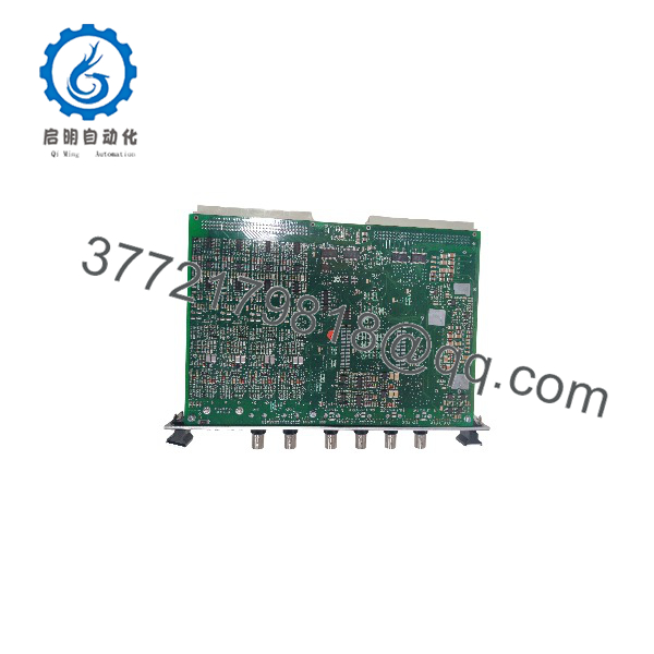
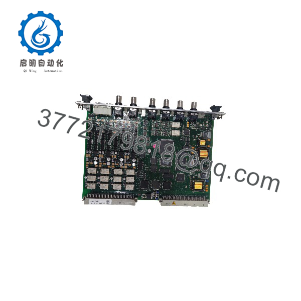
The Vibro-Meter VM600 MPC4 hardware pair (Meggitt) consists of the MPC4 Machinery Protection Card (Part Number: 200-510-071-113) and its associated IOC4T Input/Output Rear Card (Part Number: 200-510-111-034). Operating together inside VM600 ABE60x series 19-inch racks, this synchronized card set provides continuous real-time machinery protection and condition monitoring for high-value rotating plant assets.
The front MPC4 module (200-510-071-113) processes 4 independent dynamic signal channels (vibration, position, or pressure) and 2 speed/phase reference (tachometer) channels using 24-bit A/D conversion. The matching rear IOC4T module (200-510-111-034) supplies physical screw terminal connections for field sensor wiring, raw signal buffered outputs, 4-20 mA DC current outputs, discrete alarm contacts, and onboard protection relays.
Key Technical Specifications
| Parameter | Specification |
| Manufacturer | Vibro-Meter (Meggitt Sensing Systems) |
| System Platform | VM600 Machinery Protection System |
| Front Module Part Number | 200-510-071-113 (MPC4 Machinery Protection Card) |
| Rear Module Part Number | 200-510-111-034 (IOC4T Input/Output Card) |
| Dynamic Signal Inputs | 4 channels (accepts proximity probes, accelerometers, velocity transducers) |
| Tachometer / Speed Inputs | 2 channels (0.016 Hz to 50 kHz input range) |
| Signal Conversion | 24-bit resolution Analog-to-Digital Converter (ADC) |
| Onboard Relays | 4 discrete output relays (electromechanical, Form C / SPDT dry contacts) |
| Analog DC Outputs | 4 scalable 4–20 mA or 0–10 V DC outputs (on IOC4T rear card) |
| Dynamic Signal Outputs | 4 buffered raw signal outputs (front BNC connectors and rear screw terminals) |
| Form Factor | 6U Eurocard format (Front: 262 mm × 20 mm × 187 mm) |
| Operating Temperature Range | -20°C to +65°C (-4°F to +149°F) |
| Relative Humidity | 0% to 95% non-condensing |
| Safety Certification | SIL functional safety certified version |
Detailed Product Overview
The Vibro-Meter VM600 MPC4 card pair (200-510-071-113 / 200-510-111-034) forms the primary signal execution engine within the VM600 machinery protection system. Engineered for critical turbomachinery—including steam turbines, gas turbines, heavy centrifugal compressors, and boiler feed pumps—the system calculates overall peak-to-peak displacement, RMS velocity, peak acceleration, and phase angle to enforce automatic trip protection against destructive machinery faults.
The module operates across a split front/rear architecture:
- Front MPC4 Card (200-510-071-113): Houses the main digital signal processing (DSP) engine, 24-bit acquisition circuitry, VMEbus interface, and 4 front-panel BNC connectors for temporary diagnostic raw signal logging.
- Rear IOC4T Card (200-510-111-034): Installs in the exact corresponding rear slot of the VM600 mainframe. It features high-density removable screw terminals that land field sensor cables, distribute transducer excitation voltages (e.g., -24V DC for eddy-current probes), and output hardwired relay contacts and 4-20 mA signals to plant DCS and ESD systems.
Configuration is accomplished via Vibro-Meter MPS / VibroSight software over the rack’s CPU module or through the front RS-232 serial port.
VM600 MPC4 200-510-071-113 200-510-111-034
VM600 MPC4 200-510-071-113 200-510-111-034
Engineering Selection Highlights
- Matched Functional Hardware Pair: The combination of front card (200-510-071-113) and rear card (200-510-111-034) provides a complete, fully wired slot installation for 4 vibration and 2 speed channels.
- SIL Functional Safety Certified: Part number 200-510-071-113 represents the standard safety-certified revision designed for high-integrity plant trip loops.
- Comprehensive Field Signal Landing: Rear IOC4T card provides physical connection points for sensor power, raw signal buffering, 4-20 mA outputs, and dry relay contacts.
- Raw Signal Diagnostic Access: Front BNC connectors permit immediate connection of portable FFT vibration analyzers without opening cabinets or disconnecting field cables.
- High-Precision 24-Bit Processing: Executes simultaneous order tracking, band-pass filtering, and gap voltage measurement across all 4 dynamic channels.
System Compatibility & Integration Requirements
| Item / Dependency | Verified Compatibility or Requirement | Practical Note |
| Mainframe Chassis | Vibro-Meter VM600 ABE60x 19″ Rack Enclosures | Installs into standard 6U front and rear matching slots |
| Rear I/O Module | Vibro-Meter IOC4T (200-510-111-034) | Must be paired in the corresponding rear slot directly behind the MPC4 card |
| System Controller | VM600 CPUx / CPUM Controller | Enables Modbus TCP/RTU communications over the backplane VMEbus |
| Software Tools | Vibro-Meter MPS / VibroSight Software Suite | Configures channel assignment, scale factors, filter ranges, and relay logic |
| Transducer Inputs | Proximity Probes, Accelerometers, Velocity Pickups | Accepts standard voltage and current-driven vibration transducers |
Dimensions, Mounting & Connection Notes
- Form Factor: Standard 6U Eurocard format.
- Dimensions (Front Card): Height: 262 mm (10.3 in) | Width: 20 mm (0.8 in) | Depth: 187 mm (7.4 in).
- Mounting: The MPC4 card (200-510-071-113) slides into the front slot of a VM600 19-inch rack; the IOC4T card (200-510-111-034) slides into the matching rear slot. Both modules are secured using captive thumbscrews.
- Field Wiring: Sensor cables, 4-20 mA output loops, and trip relay wiring land on plug-in screw terminal blocks on the rear 200-510-111-034 card faceplate.
- Diagnostic Port: 4 front BNC connectors provide raw unbuffered AC/DC signal output for portable test instruments.
FAQ
What does the part combination 200-510-071-113 and 200-510-111-034 represent?
200-510-071-113 is the part number for the front-loading MPC4 processing card, while 200-510-111-034 is the part number for the matching IOC4T rear input/output card assembly.
Can the MPC4 200-510-071-113 card operate without the rear IOC4T card?
No. The MPC4 processing card requires the rear IOC4T module (200-510-111-034) to supply transducer excitation power, physical field cable landings, and relay output terminals.
What signal types can be connected to the 4 dynamic channels?
The channels accept inputs from eddy-current proximity probes (shaft displacement/gap), accelerometers (casing vibration), and velocity sensors.
How are raw signals accessed for diagnostic monitoring?
Buffered raw dynamic signals can be read directly from the 4 BNC connectors on the front panel of the MPC4 card using a portable vibration analyzer or oscilloscope.
Verification & Troubleshooting Notes
High-Voltage Relay Protection Hazard
Always verify that external control voltage feeds connected to the rear IOC4T (200-510-111-034) terminal block are de-energized prior to installing, removing, or wiring the card pair to prevent physical shock or unintended equipment shutdown.
1.Inspect Status LEDs:1 min.
Observe the diagnostic status LEDs on the front faceplate of the 200-510-071-113 MPC4 card upon rack power-up.
Verification: The main power/health LED displays a solid green light, confirming normal bootup and successful backplane communication.
2.Check Transducer Bias Voltages at Rear Card:2 min.
Measure the DC voltage across the sensor input terminals on the rear 200-510-111-034 IOC4T module using a digital multimeter.
Verification: The voltage matches the required transducer excitation specification (e.g., -24V DC for standard proximity probe drivers).
3.Verify Dynamic Signal Integrity at BNC Ports:3 min.
Connect an oscilloscope or portable spectrum analyzer to the front-panel BNC connectors for active dynamic channels.
Verification: The output signal shows a clean bias voltage (e.g., -8V DC to -12V DC for proximity probes) with dynamic AC vibration components visible without signal saturation or clipping.
4.Verify Front/Rear Mechanical Seating:2 min.
If the card reports hardware faults or open-circuit sensor errors, loosen the captive thumbscrews and re-seat both the 200-510-071-113 front card and 200-510-111-034 rear card firmly into the rack backplane.
Verification: The faceplates sit completely flush against the 19-inch rack frame, and captive screws hand-tighten smoothly.