WhatsApp: +86 16626708626
 Email:
 Phone: +86 16626708626
Description
Core Product Summary (Brand / Model / Key Attributes)
The Vibro-Meter VM600 MPC4 (Part Number 200-510-071-113) is a standard-version, safety-certified machinery protection card manufactured by Meggitt under the Vibro-Meter product line. Installed within VM600 ABE60x series 19-inch racks, it functions as the primary processing engine for real-time machinery protection and condition monitoring.
This module processes 4 independent dynamic signal inputs (vibration, position, or pressure) and 2 speed/phase reference (tachometer) inputs simultaneously. Operating alongside a matching IOC4T rear input/output card, the MPC4 200-510-071-113 processes high-speed sensor data, evaluates Alert and Danger alarm conditions, and triggers hardware protection relays to safeguard critical turbomachinery.
Key Technical Specifications
| Parameter | Specification |
|---|---|
| Manufacturer | Vibro-Meter (Meggitt Sensing Systems) |
| Model Designation | VM600 MPC4 |
| Part Number | 200-510-071-113 (Standard Version, Safety Certified) |
| Dynamic Signal Inputs | 4 channels (acceleration, velocity, proximity/displacement) |
| Speed / Phase Inputs | 2 tachometer channels (0.016 Hz to 50 kHz input frequency) |
| Analog-to-Digital Resolution | 24-bit data acquisition |
| Frequency Response | DC to 10 kHz (-0.1 dB); DC to 40 kHz (-3 dB) |
| Common Mode Voltage | -50 V to +50 V |
| Buffered Raw Outputs | Front-panel BNC connectors (1 V/V voltage, 0.3245 V/mA current) |
| Communication Interfaces | VMEbus (A24/D16 slave) and front-panel RS-232 configuration port |
| Dimensions (H × W × D) | 6U Eurocard format (262 mm × 20 mm × 187 mm / 10.3 in × 0.8 in × 7.4 in) |
| Weight | Approx. 0.40 kg (0.88 lb) |
| Safety Certification | SIL safety certified version scope |
Detailed Product Overview
The Vibro-Meter VM600 MPC4 200-510-071-113 Machinery Protection Card delivers continuous monitoring and emergency shutdown protection for critical rotating equipment, such as steam and gas turbines, centrifugal compressors, boiler feed pumps, and large electric motors.
The module incorporates 4 dynamic channels capable of sampling raw signals from proximity probes, accelerometers, and velocity transducers, alongside 2 auxiliary speed/phase reference channels. Equipped with 24-bit A/D converters, the card executes synchronous (order tracking) or asynchronous signal sampling to calculate overall vibration levels, peak values, shaft gap distances, and phase angles.
The card operates as part of a functional card pair: the MPC4 front-loading module executes digital signal processing and alarm evaluation, while an associated IOC4T card mounted at the rear of the rack provides physical field cable landings, DC analog outputs (4-20 mA / 0-10V), discrete control inputs, and alarm relay contacts.
Front-panel BNC connectors provide direct access to raw, unbuffered dynamic signals for temporary diagnostic testing using portable FFT analyzers. The card communicates with central rack controllers via the internal VMEbus and can be configured using Vibro-Meter MPS / VibroSight software tools.
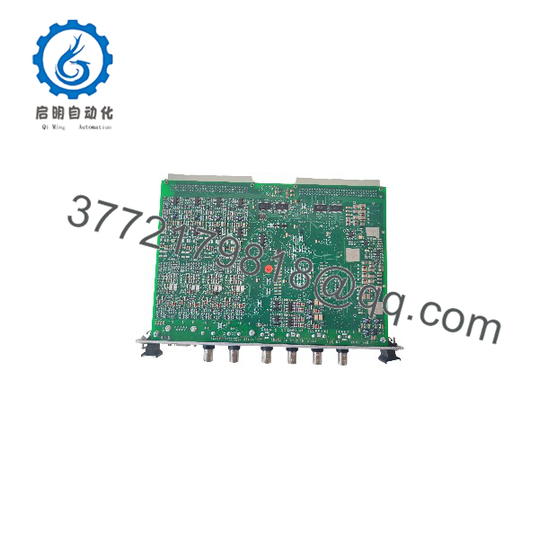
VM600 MPC4 200-510-071-113
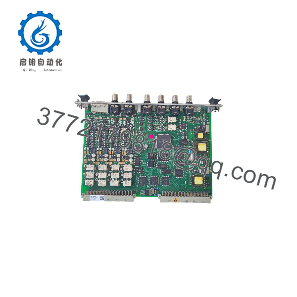
VM600 MPC4 200-510-071-113
Engineering Selection Highlights
- 4+2 Dual Function Processing: Evaluates 4 dynamic vibration channels and 2 tachometer channels simultaneously within a single 6U card slot.
- Integrated Safety Certification: The 200-510-071-113 designation represents the standard-version MPC4 card certified for functional safety (SIL) applications.
- High-Precision Signal Conversion: Uses 24-bit data acquisition engines for high signal-to-noise ratio and precise order-tracking analysis.
- Raw Signal BNC Access: Front-panel BNC connectors allow real-time signal analysis without disturbing permanent field wiring.
- Dual Bus Communication: Features VMEbus backplane support for system-level networking plus an RS-232 port for direct local maintenance access.
System Compatibility & Integration Requirements
| Item / Dependency | Verified Compatibility or Requirement | Practical Note |
|---|---|---|
| Mainframe Chassis | Vibro-Meter VM600 ABE60x 19″ Rack Enclosures | Installs into standard 6U front-loading slots |
| Rear Termination Module | Vibro-Meter VM600 IOC4T Card | Requires an IOC4T card in the corresponding rear slot for field cabling |
| System Controller | VM600 CPUx / CPUM Rack Controller | Required for Ethernet and Modbus system networking over the VMEbus |
| Configuration Software | Vibro-Meter MPSx / VibroSight Software | Used to configure gain, filter bands, alarm setpoints, and tracking parameters |
| Transducer Inputs | Proximity Probes, Accelerometers, Velocity Pickups | Accepts voltage and current-modulated sensor signals |
Dimensions, Mounting & Connection Notes
- Form Factor: Standard 6U Eurocard.
- Dimensions: Height: 262 mm (10.3 in) | Width: 20 mm (0.8 in) | Depth: 187 mm (7.4 in).
- Weight: 0.40 kg (0.88 lb).
- Mounting: Inserts into the front panel of a VM600 19-inch rack and is secured with top and bottom captive thumbscrews.
- Front Panel Connectors: 4 BNC connectors for raw dynamic signal observation; 1 RS-232 serial port for local configuration.
- Rear Panel Interfacing: All permanent field wiring (sensor excitation, signal loops, relays) connects directly to the paired rear IOC4T card.
FAQ
What is the difference between MPC4 part numbers?
The part number 200-510-071-113 represents the standard, safety-certified build of the MPC4 card. Other revision suffixes indicate different hardware variations, such as non-certified standard modules, separate-circuit variants, or SIL-only variants.
Can the MPC4 200-510-071-113 function without a rear card?
No. The MPC4 module requires a matching rear IOC4T I/O card to provide physical signal terminals, sensor power supplies, and relay outputs.
How are the raw vibration signals accessed for diagnostic testing?
Buffered raw dynamic signals can be measured directly from the 4 BNC connectors on the front faceplate of the MPC4 card using portable diagnostic equipment.
What software is used to configure the MPC4 card?
The card is configured using Vibro-Meter MPS (Machinery Protection System) software or VibroSight software via the front RS-232 port or over the rack’s Ethernet network through a CPU module.
Verification & Troubleshooting Notes
1
Inspect Status LEDs
1 min
1.Inspect Status LEDs:1 min.
Observe the front-panel diagnostic LEDs on the MPC4 module upon applying rack power. Verify that the power/health LED illuminates green and that no red diagnostic fault indicators remain active. Verification: The status LED displays a continuous green state indicating successful boot and self-test execution.
2
Verify Raw Signal Output at BNC Ports
3 min
2.Verify Raw Signal Output at BNC Ports:3 min.
Connect an oscilloscope or portable spectrum analyzer to the front-panel BNC connectors for the active dynamic channels. Check for clean AC/DC voltage signals corresponding to transducer bias and dynamic vibration. Verification: The output signal shows the expected sensor bias voltage (e.g., -8V DC to -12V DC for proximity probes) without clipping or signal dropouts.
3
Check Front and Rear Hardware Seating
2 min
3.Check Front and Rear Hardware Seating:2 min.
If channel communication or sensor signal loss occurs, verify that the front MPC4 card and rear IOC4T card are fully aligned and that the captive thumbscrews are firmly hand-tightened into the rack frame. Verification: Module faceplates align flush with adjacent rack slots, and multi-pin backplane connectors make complete contact.
4
Confirm RS-232 Serial Communication
2 min
4.Confirm RS-232 Serial Communication:2 min.
Connect a serial cable from a maintenance laptop to the MPC4 front-panel RS-232 port. Open the VM600 MPS configuration software to poll module status and verify configuration parameter matching. Verification: The software establishes a online link and reads back active channel configurations and alarm setpoints.