
 WhatsApp: +86 16626708626
 Email:
  Phone: +86 16626708626
Description
Key Technical Specifications
| Parameter | Specification |
|---|---|
| Manufacturer | Waukesha |
| Part Number | E740401 |
| Product Name | Detonation Sensing Module |
| System | Waukesha Custom Engine Control |
| Function | Detonation / knock sensing |
| Application | Industrial gas engine control and protection |
| Signal Role | Processes engine detonation-related sensor signals |
| Control Interface | Interfaces with the associated Waukesha engine-control architecture |
| Operating Voltage | Verify against the engine-specific documentation before installation |
| Sensor Configuration | Verify against the installed engine and harness configuration |
| Dimensions | Do not use aftermarket dimensional data as a substitute for OEM mechanical drawings |
| Replacement Method | Match exact part number, connector configuration, hardware revision, and installed engine system |
Available supplier records consistently identify E740401 as a Waukesha detonation sensing module, although some third-party listings contain conflicting product descriptions. For this reason, the part number and physical identification on the installed module should take precedence over generic catalog descriptions.
Product Introduction
The Waukesha E740401 is a Detonation Sensing Module used within Waukesha Custom Engine Control systems for industrial gas-engine applications. Its primary function is to process signals associated with combustion knock or detonation so the engine-control system can identify abnormal combustion conditions.
The module is particularly relevant when maintaining legacy Waukesha engine-control equipment where an exact replacement is required. Because aftermarket listings identify E740401 as a refurbished or surplus component, buyers should verify the exact part number, connector arrangement, condition, and engine-control configuration before installation.
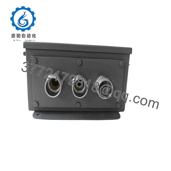
E740401
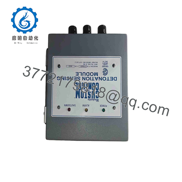
E740401
Installation & Configuration Guide
Stage 1 — Pre-Installation Preparation
Estimated time: 30–60 minutes, excluding engine-specific shutdown procedures.
- Place the engine and associated control system in the manufacturer-approved shutdown state.
- Apply the site’s lockout/tagout (LOTO) procedure before opening the control cabinet.
- Isolate all applicable electrical and ignition-related energy sources.
- Record existing controller alarms, diagnostic codes, and relevant engine-control parameters.
- Photograph the existing E740401 installation before disconnecting any wiring.
- Confirm that the replacement is marked E740401 and compare connector positions and physical construction with the installed module.
- Use appropriate ESD protection when handling the module or exposed circuit-board assemblies.
⚠️ Do not assume a generic 24 VDC specification. Third-party sources publish nominal 24 VDC information, but the available evidence does not establish the complete electrical specification for every installation. Verify the supply requirements from the applicable Waukesha engine-control documentation before energizing the replacement.
Stage 2 — Removing the Existing Module
- Verify that the engine is fully shut down and electrically isolated.
- Remove the control-panel cover or access hardware according to the engine service procedure.
- Label every connector and wire before removal.
- Disconnect the module carefully without pulling on individual conductors.
- Release the module’s mechanical retainers or mounting hardware.
- Remove the existing and place it in an ESD-safe container.
- Inspect the connector pins, harness plugs, mounting area, and surrounding wiring for:
- Corrosion
- Loose terminals
- Oil or moisture contamination
- Damaged insulation
- Bent connector contacts
- Evidence of overheating
Keep the removed module until commissioning is complete. It can provide useful reference information if the replacement produces unexpected diagnostic behavior.
Stage 3 — Installing the Replacement Module
- Confirm the replacement part number is .
- Compare the replacement physically against the removed module.
- Check connector orientation and mechanical mounting points.
- Do not force a connector or mounting interface that does not align naturally.
- Install the module using the original mounting hardware or the engine manufacturer’s specified hardware.
- Reconnect all wiring according to the photographs, labels, and machine documentation.
- Inspect each connector for complete seating and positive retention.
- Verify that sensor wiring remains separated from sources of electrical interference where required by the original installation.
- Recheck all connections before restoring power.
⚠️ Do not modify sensor wiring, connector pin assignments, or engine-control parameters simply to make a replacement module fit. compatibility must be established at the complete engine-control-system level.
Stage 4 — Power-On & Testing
- Perform a final visual inspection before energizing the system.
- Restore power according to the Waukesha engine-control startup procedure.
- Check the controller for initialization faults or communication-related alarms.
- Confirm that the engine-control system recognizes the installed sensing hardware.
- Review stored diagnostic information.
- Start the engine only when the applicable commissioning procedure permits it.
- Monitor detonation-related diagnostics during controlled operation.
- Compare sensor behavior and alarm status against known-good operating conditions.
- Perform a controlled load test when required by the engine service procedure.
- Record the final module identification, engine configuration, diagnostic status, and commissioning results.
⚠️ Do not treat replacement of as proof that the module caused the original fault. Detonation-related problems can also originate from sensor wiring, sensor mounting, electrical noise, engine operating conditions, ignition components, or other parts of the engine-control system.
Frequently Asked Questions (FAQ)
Is Waukesha a detonation sensing module?
Yes. Multiple supplier and repair records identify as a Waukesha Detonation Sensing Module associated with Custom Engine Control systems.
Is still manufactured by Waukesha?
The available sources do not provide sufficient authoritative OEM documentation to establish its current manufacturing lifecycle. Several aftermarket suppliers treat it as a legacy component and offer refurbished or surplus units. Confirm current OEM lifecycle status before planning a long-term spare strategy.
Can I replace directly?
A direct replacement should be based on the exact part number plus the installed engine-control configuration. Verify connectors, hardware revision, harness compatibility, and applicable engine documentation before installation.
Does the replacement module require parameter programming?
Do not assume that is universally plug-and-play or universally field-programmable. The required configuration depends on the specific Waukesha engine-control architecture. Back up existing control parameters and follow the applicable service documentation.
What condition can I expect when purchasing ?
Market listings include refurbished and surplus units. One supplier currently identifies its offering as refurbished, while other catalogs list the part as an available aftermarket component. The actual condition, test procedure, warranty, and packaging should be confirmed with the supplier before purchase.
What should I check if a replacement does not resolve a detonation alarm?
Check the complete signal path rather than immediately condemning the module. Inspect detonation sensors, sensor mounting, harness continuity, connector condition, grounding/shielding, electrical interference, ignition-related components, and engine operating conditions. A module replacement alone does not establish the root cause.
What information should I provide when sourcing an replacement?
Provide the exact part number, photographs of the existing module and connectors, engine model, engine-control system information, module condition required, and any diagnostic codes. This information reduces the risk of receiving a mechanically similar but electrically incompatible legacy module.



