
 WhatsApp: +86 16626708626
 Email:
  Phone: +86 16626708626
Description
Key Technical Specifications
| Parameter | Value |
|---|---|
| Model | 5448-890 |
| Brand | Woodward |
| Product Series | SPM-D10 |
| Product Type | Digital Generator Synchronizer |
| Configuration | SPM-D1010B |
| Synchronization | Single-breaker |
| Generator Application | Three-phase AC generator |
| Generator Voltage Measurement | 1-phase / 2-wire |
| Busbar Voltage Measurement | 1-phase / 2-wire |
| Power Supply | 24 VDC |
| Power Supply Tolerance | ±25% |
| Maximum Power Consumption | 10 W |
| Frequency Control | Discrete raise/lower speed bias |
| Voltage Control | Discrete raise/lower voltage bias |
| Breaker Control | Synchronization / breaker control |
| Dimensions | 144 × 72 × 122 mm |
| Switching Voltage | Maximum 250 VAC |
| Operating Principle | Microprocessor-based digital synchronization |
| Successor | 8440-2166 SPM-D2-1010B |
Woodward’s catalog specifies the 5448-890 as the 100 VAC version of the standard SPM-D10, with one-phase/two-wire generator and busbar voltage measurement and discrete speed/voltage bias control.
Product Introduction
The Woodward 5448-890 SPM-D10 is a microprocessor-based digital synchronizer for three-phase AC generator systems. It compares generator and bus conditions and provides automatic frequency, phase, and voltage matching before breaker closure. The standard 5448-890 configuration uses 100 VAC voltage measurement and a 24 VDC control supply.
This version uses discrete raise/lower outputs for generator speed and voltage bias. It is intended for a single-breaker synchronization application. The model is now legacy hardware; Woodward’s published part-number map assigns 8440-2166 SPM-D2-1010B as its successor.
Installation & Configuration Guide
Stage 1: Pre-Installation Preparation — 5–10 Minutes
⚠️ Safety First: Generator synchronization involves live AC voltage and breaker control. Place the generator and switchgear in an approved safe state before removing the synchronizer. Follow the site’s electrical isolation and lockout/tagout procedures.
Tools Required:
- ESD wrist strap
- Digital multimeter
- Insulated screwdriver
- Wire labels
- Smartphone or camera
- Current generator control drawings
Data Backup:
- Record the complete 5448-890 nameplate information.
- Photograph every terminal connection before removal.
- Record generator and bus voltage transformer wiring.
- Document speed-bias and voltage-bias connections.
- Record breaker-control wiring.
- Document all programmed synchronization parameters.
- Record the existing firmware/configuration information where accessible.
⚠️ Do not assume that a physically identical replacement has the same configuration. Synchronization parameters directly affect breaker-closing behavior.
Stage 2: Removing the Old Module — 5 Minutes
- Verify the generator is isolated from the electrical bus as required by the maintenance procedure.
- Remove control power according to the applicable Woodward procedure.
- Confirm absence of hazardous voltage using the approved test method.
- Label every conductor.
- Photograph terminal positions and wire numbers.
- Disconnect the generator and bus sensing circuits.
- Disconnect speed-bias, voltage-bias, and breaker-control wiring.
- Remove the 5448-890 from its panel mounting arrangement.
⚠️ Keep the original unit until commissioning is complete. Its terminal arrangement and configuration are valuable references.
Stage 3: Installing the New Module — 5–10 Minutes
- Verify the replacement part number and voltage configuration.
- Confirm that the application requires the 100 VAC 5448-890 configuration.
- Mount the synchronizer securely.
- Reconnect generator voltage sensing.
- Reconnect busbar voltage sensing.
- Reconnect 24 VDC power.
- Reconnect discrete speed-bias and voltage-bias outputs.
- Reconnect breaker-control circuits.
- Compare every conductor against the original photographs and electrical drawings.
- Verify terminal tightness before energizing.
Self-Checklist:
- 5448-890 verified
- 100 VAC sensing configuration verified
- 24 VDC supply verified
- Generator sensing wiring checked
- Bus sensing wiring checked
- Speed-bias wiring checked
- Voltage-bias wiring checked
- Breaker wiring checked
- Parameter configuration documented
Stage 4: Power-On & Testing — 10–20 Minutes
- Perform a final wiring inspection before applying control power.
- Measure the DC supply voltage.
- Verify the generator and bus sensing circuits against the electrical drawings.
- Apply control power.
- Check the synchronizer display and status indicators.
- Verify the measured generator voltage.
- Verify the measured busbar voltage.
- Confirm frequency and phase measurements.
- Perform the approved simulation or commissioning test of speed and voltage bias.
- Verify breaker permissive logic without immediately closing the breaker.
- Confirm the configured synchronization window and breaker timing.
- Perform the final synchronization test under the plant’s approved commissioning procedure.
⚠️ Do not bypass synchronism-check or breaker permissive circuits merely to prove the replacement works. A synchronizer replacement should be commissioned as part of the complete generator protection and breaker-control chain.
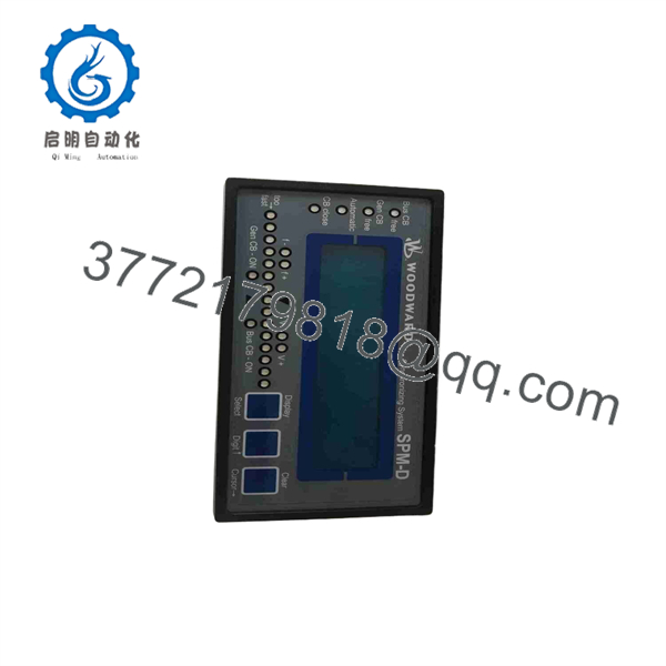
5448-890 SPM-D10
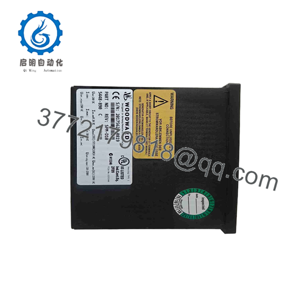
5448-890 SPM-D10
Frequently Asked Questions (FAQ)
What is the Woodward 5448-890 SPM-D10?
The 5448-890 is a Woodward SPM-D10 digital synchronizer for three-phase AC generator applications. The standard version is designed for single-breaker synchronization and uses discrete raise/lower outputs for speed and voltage bias.
What voltage configuration does the 5448-890 use?
The 5448-890 is the 100 VAC version of the standard SPM-D10. Woodward separately lists 8440-1019 for the 400 VAC version, so these part numbers should not be treated as interchangeable without checking the actual voltage-sensing architecture.
What is the power supply requirement?
The 5448-890 uses a 24 VDC supply. A secondary technical listing specifies a ±25% supply tolerance and maximum power consumption of approximately 10 W.
Is 5448-890 obsolete?
Yes. The 5448-890 belongs to the older SPM-D family. Woodward’s successor documentation maps 5448-890 / SPM-D1010B to 8440-2166 / SPM-D2-1010B. A Woodward support statement also describes the older SPM-D products as entering accelerated phase-down because of processor obsolescence.
What is the direct replacement for Woodward 5448-890?
Woodward’s published part-number map identifies 8440-2166, SPM-D2-1010B as the successor to 5448-890, SPM-D1010B. Treat this as a documented successor mapping, but still verify the application-specific wiring, sensing voltage, configuration, and commissioning requirements before installation.
Can I replace a 5448-890 with 8440-1019?
Do not make that substitution based only on the family name. Woodward identifies 5448-890 as the 100 VAC version and 8440-1019 as the 400 VAC version. The voltage-sensing architecture must match the installed generator and bus voltage transformers.
Does replacing the synchronizer erase the generator controller settings?
The synchronizer is a separate control device, so replacing it does not inherently erase settings stored elsewhere in the generator controller. However, the ‘s own synchronization parameters must be documented and reproduced as required. Before removing the old unit, record its configuration and verify the new unit during commissioning.



