
 WhatsApp: +86 16626708626
 Email:
  Phone: +86 16626708626
Description
3. Key Technical Specifications
| Parameter | Value |
|---|---|
| Manufacturer | Woodward |
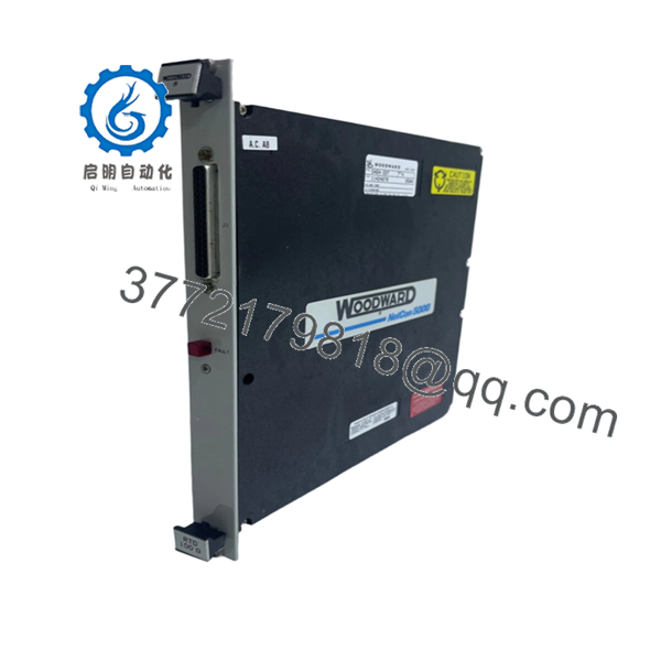
| Model Number | 5464-337 Rev H |
| Product Type | Analog Input Module |
| Platform | Woodward 5400 Series / MicroNet |
| Input Voltage | 24 VDC |
| Power Supply Range | 10–60 VDC |
| Isolation Protection | 3000 VDC |
| Update Time | 5 ms |
| Operating Temperature | -25 °C to +70 °C |
| Channel Type | Analog Input |
| Weight | Approximately 0.9 kg (2 lb) |
| Country of Manufacture | USA |
| Revision | Rev H |
| Installation Type | Rack-Mounted Control Module |
Compatibility Note: Woodward documentation identifies 5464-337 as a Semi-Isolated RTD 100 input module within the MicroNet family. Verify firmware revision and application configuration before replacement in operating turbine control systems.
4. Product Introduction
The WOODWARD 5464-337 Rev H is an analog input module used in Woodward 5400 Series and MicroNet turbine control systems. It acquires field analog signals and converts them for processing by the controller, supporting power generation, compressor control, and critical rotating equipment applications.
In field deployments of legacy MicroNet systems, this module is commonly selected when maintaining existing control architectures without modifying application logic. Rev H units are often preferred because they allow direct replacement of installed hardware while preserving existing wiring and cabinet layouts. Verify exact module function and firmware compatibility against the installed system documentation before installation.

- 5464-337 Rev H
- 5464-337 Rev H
5. Installation & Configuration Guide
Stage 1: Pre-Installation Preparation (10 Minutes)
⚠️ Safety First
- Notify operations personnel of planned control system downtime.
- Place the process in a verified safe state.
- Apply lockout/tagout procedures.
- Remove control power.
- Wait at least 5 minutes for internal capacitors to discharge.
Tools Required
- ESD wrist strap
- ESD work mat
- PH1 screwdriver
- Fluke 115 multimeter or equivalent
- Wire markers
- Smartphone for documentation
- Flashlight
Data Backup
- Export controller logic and configuration files.
- Record controller IP addresses and communication settings.
- Photograph all terminal wiring.
- Photograph all DIP switch and jumper positions.
- Record the existing module firmware revision if accessible.
⚠️ Critical: Document everything before touching the hardware. The photos often save more downtime than the backup files.
Stage 2: Removing the Old Module (5–10 Minutes)
- Remove the front cover or chassis access panel.
- Label every field wire before disconnecting.
- Disconnect terminal blocks carefully. Do not pry connectors with a screwdriver.
- Release rack retaining screws or locking tabs.
- Pull the module straight out.
⚠️ Do not rock the card side-to-side. Backplane connectors on older MicroNet racks can crack or bend.
- Inspect:
- Backplane pins
- Connector sockets
- Dust accumulation
- Signs of overheating
⚠️ Keep the original module on-site until the replacement has completed operational testing.
Stage 3: Installing the New Module (10 Minutes)
- Connect ESD wrist strap to a verified ground point.
- Confirm:
- Model number = 5464-337
- Revision level acceptable for site standards
- No shipping damage
- Configuration Clone (Crucial)
- Match every DIP switch position.
- Match every jumper position.
- Verify node address settings.
- Verify termination resistor settings.
❗This is the most common rookie mistake, but it happens constantly. Take a picture before you pull it. I can’t stress this enough.
- Insert the module into the rack guides.
- Push evenly until fully seated.
- Tighten retaining hardware.
- Reconnect wiring using proper torque values from the Woodward installation manual.
Self-Checklist
- DIPs match original
- Jumpers match original
- Wiring secured
- Module fully seated
- Retaining tabs locked
Stage 4: Power-On & Testing (10–15 Minutes)
Pre-Power Check
- Verify no shorts exist on the 24 V rail using a multimeter.
- Confirm ground continuity.
- Verify terminal polarity.
Power-Up Procedure
- Energize the control rack only.
- Observe startup LEDs.
- Verify:
- RUN LED = Green
- ERR LED = Off
- Connect engineering workstation.
- Confirm:
- Module detected
- Correct firmware revision
- Correct node addressing
- Communication status healthy
- Download saved configuration if required.
- Simulate analog inputs.
- Verify controller receives expected values.
- Return field devices to service.
⚠️ Troubleshooting Note
- Solid red ERR LED: firmware incompatibility or configuration mismatch.
- No communications: verify addressing, backplane seating, and network settings.
- Unstable analog values: inspect shielding and grounding practices.
Quality Control & Functional Verification SOP
1. Inbound Inspection & Traceability
Every incoming 5464-337 module undergoes:
- OEM part number verification.
- Serial number inspection.
- Anti-counterfeit label inspection.
- Visual examination under magnification.
- Verification of:
- No corrosion
- No rework marks
- No damaged traces
- No UV yellowing
- Accessory audit:
- Original packaging if available
- Documentation
- Factory labels
2. Live Functional Testing
Testing is performed using a dedicated Woodward-compatible simulation rack.
Procedures include:
- Power-on self-test.
- LED status verification.
- Communication handshake testing.
- Analog signal simulation.
- Full-scale I/O verification.
- Continuous burn-in testing exceeding 24 hours.
- Thermal monitoring during operation.
A formal test report is generated and archived.
Test videos and photos are available upon request.
3. Electrical Parameter Testing
Performed using calibrated instruments.
Tests include:
- 500 V Megger insulation resistance test (>10 MΩ target)
- Ground continuity verification
- Power rail validation
- Hipot testing where application permits
4. Firmware & Configuration Verification
- Firmware revision recorded.
- Hardware revision documented.
- DIP switch positions photographed.
- Configuration labels archived.
5. Final QC & Packaging
- QC inspector sign-off.
- ESD-safe packaging.
- Anti-static bag sealing.
- Bubble wrap protection.
- Heavy-duty corrugated carton.
- QC Passed label applied with inspection date.
Common Replacement Pitfalls From Field Experience
❗ Firmware Revision Mismatch
A replacement module may physically fit but still fail communications.
I’ve seen a gas turbine outage where maintenance swapped a newer module into an older rack. The controller reported communication timeouts for nearly two days. The root cause was a firmware jump between generations.
Avoidance:
- Record existing firmware before removal.
- Request matching firmware ranges when ordering.
- Verify compatibility with the installed MicroNet release.
❗ DIP Switch Misconfiguration
This causes more startup failures than defective hardware.
A single incorrect node address can take an entire network segment offline.
Avoidance:
- Photograph switches before removal.
- Replicate every position exactly.
- Verify termination settings twice.
❗ Terminal Block and Wiring Differences
Even when part numbers look similar, revision changes can affect signal assignments.
I’ve watched technicians wire from memory and spend hours chasing nonexistent controller faults.
Avoidance:
- Use wiring drawings.
- Verify every terminal point.
- Check shield grounding methods.
❗ Power Supply Loading
Older cabinets often operate close to power supply limits.
Adding replacement hardware without checking total current draw can create intermittent resets.
Avoidance:
- Calculate total rack consumption.
- Maintain at least 20% power margin.
- Verify supply voltage under load.
❗ Electrostatic Discharge (ESD)
This one is expensive.
I once watched an engineer handle a board during winter without a wrist strap. The card powered up, emitted smoke within seconds, and became scrap.
Avoidance:
- Grounded wrist strap.
- ESD mat.
- Store modules in anti-static packaging until installation.
Keep these checks in mind and you’ll save yourself 90% of typical rework time.
6. Frequently Asked Questions (FAQ)
Q1: Can I hot-swap the WOODWARD 5464-337 Rev H while the system is running?
No. Treat this module as non-hot-swappable unless your exact MicroNet architecture and OEM documentation explicitly allow it.
Pulling the card under power can corrupt communications, damage the backplane, or create unpredictable controller behavior. Shut down the rack first.
Q2: Is the 5464-337 obsolete?
Yes.
Woodward identified the 5464-337 as an obsolete module family member and announced replacement programs for several legacy input modules. Most available inventory today comes from surplus stock, refurbished inventory, or strategic spare-part holdings.
Q3: Is your inventory genuinely new?
That depends on the stock source.
For transparency:
- New Original / New Surplus = Unused OEM inventory stored after project cancellation or spare-part liquidation.
- Refurbished (Tested) = Previously installed unit that passed functional and electrical testing.
Always request photographs of the actual unit before purchase.
Q4: Will I lose my control logic if I remove the module?
Normally no.
The 5464-337 functions as an I/O module rather than the primary controller CPU. Logic typically resides within the main controller.
However, always back up the complete system before maintenance. I’ve seen plants assume logic was safe, only to discover undocumented configuration dependencies afterward.
Q5: What should I use if the 5464-337 is unavailable?
That depends on:
- Existing controller generation
- Firmware revision
- Application requirements
- RTD sensor configuration
Woodward published replacement paths for several obsolete input modules, but compatibility must be verified against the specific MicroNet hardware revision and application software. Do not assume a newer card is plug-and-play.
Q6: Why are surplus units often cheaper than OEM pricing?
Because they typically come from:
- Plant spare-part inventories
- Project overruns
- Decommissioned facilities
- Distributor excess stock
The hardware may be unused, but it does not usually include OEM support contracts or factory warranty coverage. That reduces acquisition cost substantially.
Q7: What should I verify before ordering a replacement?
At minimum:
- Part number: 5464-337
- Hardware revision: Rev H
- Firmware version
- Rack type
- Terminal configuration
- Existing field wiring arrangement
The fastest way to avoid downtime is sending photos of the installed module label, front panel, and wiring before placing the order. That five-minute check prevents most compatibility mistakes.


