
 WhatsApp: +86 16626708626
 Email:
  Phone: +86 16626708626
Description
3. Key Technical Specifications
| Parameter | Value |
|---|---|
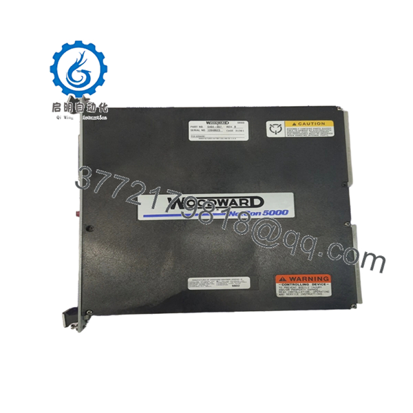
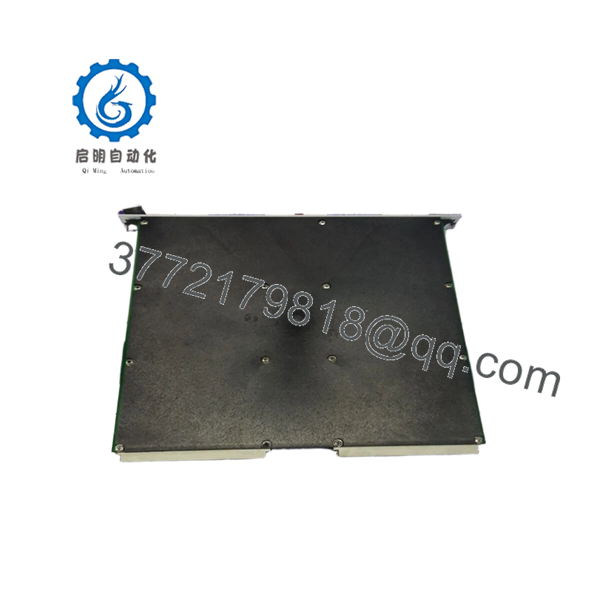
| Manufacturer | Woodward |
| Model Number | 5464-657 Rev B |
| Product Family | MicroNet Control System |
| Product Type | Control Interface Module |
| Installation | Rack/Panel System Integration |
| Platform Compatibility | Woodward MicroNet Series |
| Communication Integration | MicroNet System Backplane |
| Power Supply | System Dependent |
| Revision Level | Rev B |
| Operating Environment | Industrial Control Applications |
| Application Areas | Turbines, Compressors, Engines, Power Generation |
| Mounting Method | Chassis Mounted |
| Country of Origin | USA |
| Condition Available | New Surplus / Tested Refurbished |
Compatibility Note: Woodward MicroNet systems contain multiple hardware generations, including Simplex, Redundant, and TMR architectures. Verify exact chassis type, CPU generation, firmware revision, and I/O mapping before installation. Module compatibility inside MicroNet systems is heavily revision-dependent.
4. Product Introduction
The WOODWARD 5464-657 Rev B is a MicroNet platform control module used in turbine, compressor, engine, and power generation control systems. It operates within the Woodward MicroNet architecture, supporting real-time control functions, operator interaction, and system-level integration.
In field service environments, Rev B hardware is typically encountered in long-life installations where maintaining existing control logic and cabinet layouts is more practical than migrating to a newer platform. Before replacement, engineers should verify firmware compatibility and installed chassis revisions because MicroNet hardware revisions are not universally interchangeable.

- 5464-657 Rev B
- 5464-657 Rev B
5. Installation & Configuration Guide
Stage 1: Pre-Installation Preparation (10 Minutes)
⚠️ Safety First
- Notify plant operations of scheduled downtime.
- Bring the machine or process to a safe shutdown condition.
- Apply lockout/tagout procedures.
- Remove all control power sources.
- Wait a minimum of 5 minutes before opening the cabinet.
Tools Required
- ESD wrist strap
- ESD mat
- PH1 screwdriver
- Fluke 115 multimeter
- Label printer or wire markers
- Smartphone camera
- Flashlight
Data Backup
- Upload and archive current control logic.
- Export configuration files.
- Record controller IP addresses.
- Photograph:
- Wiring terminals
- Module labels
- DIP switches
- Jumpers
- Rack layout
❗Do not trust old drawings blindly. I’ve opened cabinets where the field wiring no longer matched the prints from three shutdowns ago.
Stage 2: Removing the Old Module (5–10 Minutes)
- Open cabinet access panels.
- Identify the target module.
- Label all cables and terminal blocks.
- Disconnect field wiring carefully.
- Release retaining screws.
- Pull module straight outward using extraction handles if fitted.
⚠️ Do not twist the module during removal.
Older MicroNet backplanes can suffer connector damage if the card is pulled unevenly.
- Inspect:
- Connector pins
- Backplane condition
- Dust contamination
- Signs of overheating
⚠️ Retain the original module until commissioning is complete.
Stage 3: Installing the New Module (10 Minutes)
- Wear a grounded ESD wrist strap.
- Verify:
- Part number = 5464-657
- Revision = Rev B
- No transport damage
Configuration Clone (Crucial)
- Compare old and replacement hardware.
- Duplicate:
- DIP switch positions
- Jumper settings
- Address configurations
- Termination settings
❗This is the most common rookie mistake, but it happens constantly. Take a picture before you pull it. I can’t stress this enough.
- Insert module into chassis guides.
- Seat the card fully.
- Tighten retaining screws.
- Reconnect all wiring according to documented labels.
Self-Checklist
- Part number verified
- Rev level verified
- DIPs copied
- Wiring secured
- Card fully seated
- Retaining hardware locked
Stage 4: Power-On & Testing (10–15 Minutes)
Pre-Power Check
- Verify 24 V rail integrity.
- Check for shorts using a multimeter.
- Verify cabinet grounding.
Power-Up Procedure
- Energize the control rack only.
- Observe startup sequence.
- Verify LED indications.
- Connect engineering workstation.
- Confirm:
- Module recognition
- Network communication
- Firmware compatibility
- Correct addressing
- Restore saved configuration if required.
- Verify all assigned I/O.
- Return field devices to service gradually.
⚠️ Troubleshooting Note
- Solid red fault LED often indicates firmware incompatibility.
- No communication usually points to addressing errors, switch settings, or backplane connection issues.
- Intermittent faults frequently trace back to loose grounding or marginal power supplies.
Quality Control & Functional Verification SOP
1. Inbound Inspection & Traceability
Each 5464-657 Rev B module undergoes:
- OEM identification verification.
- Serial number recording.
- Anti-counterfeit inspection.
- Visual inspection under magnification.
Inspection criteria:
- No corrosion
- No scratches across PCB traces
- No repaired solder joints
- No UV discoloration
- No damaged connectors
Accessory verification includes:
- Original labels
- Factory packaging when available
- Documentation and certificates
2. Live Functional Testing
Testing is performed on a genuine Woodward-compatible MicroNet test rack.
Verification process:
- Power-on self-test.
- LED sequence verification.
- Backplane communication checks.
- Simulated I/O testing.
- Communication handshake testing.
- 24-hour continuous operation test.
- Thermal monitoring during load operation.
A formal test report is generated for each tested unit.
Test photos and operational videos are available upon request.
3. Electrical Parameter Testing
Testing includes:
- 500 V insulation resistance test
- Ground continuity verification
- Supply rail verification
- Hipot testing where applicable
Target insulation resistance:
- Greater than 10 MΩ
4. Firmware & Configuration Verification
- Firmware revision recorded.
- Hardware revision documented.
- Configuration labels archived.
- DIP switch positions photographed.
5. Final QC & Packaging
- QC approval sign-off.
- Anti-static ESD packaging.
- Sealed protective bag.
- Multi-layer bubble wrap.
- Heavy-duty export carton.
- QC Passed label with inspection date.
Common Replacement Pitfalls From Real Plant Shutdowns
❗ Firmware Revision Mismatch
This problem causes more downtime than defective hardware.
I’ve seen engineers replace a working MicroNet module with a newer revision and spend two days chasing communication alarms. The hardware was fine. The firmware wasn’t.
Avoidance:
- Record firmware before removal.
- Request revision verification before shipment.
- Check compatibility matrices before installation.
❗ DIP Switch Errors
A single incorrect switch setting can prevent startup.
I’ve watched experienced technicians lose six hours because one node address switch was moved accidentally during installation.
Avoidance:
- Photograph everything.
- Verify every switch twice.
- Compare against system drawings.
❗ Wiring Assumptions
Never wire from memory.
Even within the same product family, hardware revisions can introduce subtle changes.
Avoidance:
- Verify pin assignments.
- Confirm shield terminations.
- Review OEM drawings.
❗ Power Supply Margin
Older control cabinets often run closer to supply limits than operators realize.
A replacement module may trigger voltage instability if the power supply is already overloaded.
Avoidance:
- Measure supply voltage under load.
- Maintain at least 20% capacity reserve.
- Verify rack power calculations.
❗ Electrostatic Discharge (ESD)
This failure usually happens before commissioning even begins.
I once watched a technician handle a control card in winter without grounding. The board powered up once and never again.
Avoidance:
- ESD mat.
- Ground strap.
- Anti-static storage.
Keep these checks in mind and you’ll save yourself 90% of typical rework time.
6. Frequently Asked Questions (FAQ)
Q1: Can I hot-swap the WOODWARD 5464-657 Rev B?
No.
Unless Woodward documentation for your exact chassis explicitly allows online replacement, shut the system down first. Pulling a module under power can damage the backplane or generate unpredictable controller faults.
Q2: Is the 5464-657 Rev B obsolete?
Yes, in most installations it is considered legacy hardware.
Many MicroNet systems remain operational for 15–25 years, which means replacement parts are commonly sourced from strategic spare inventories, surplus stock, or professionally tested refurbished inventory. MicroNet lifecycle documentation identifies multiple legacy module families that have transitioned into replacement programs.
Q3: Is this genuinely new hardware?
It depends on stock origin.
New Original / New Surplus generally means unused OEM inventory retained after project cancellation, plant expansion changes, or distributor liquidation.
Refurbished (Tested) means previously installed hardware that has completed inspection and functional testing.
Request actual photographs before purchasing.
Q4: Will removing this module erase my control logic?
Normally no.
The application logic usually resides within the MicroNet CPU rather than the field module.
That said, always perform a complete backup first. Field modifications and undocumented configuration dependencies can surprise even experienced maintenance teams.
Q5: What if Rev B is unavailable?
Verify approved replacement paths through Woodward documentation and compatibility matrices.
Do not assume a newer revision is automatically compatible. MicroNet hardware compatibility often depends on:
- CPU type
- Firmware level
- Coder version
- Chassis architecture
Several MicroNet module families require minimum revision levels when used with newer CPU generations.
Q6: Why is surplus inventory usually cheaper than OEM pricing?
Because the inventory often originates from:
- Plant spare stock
- Shutdown projects
- Decommissioned facilities
- Distributor overstock
The hardware may be unused, but it typically does not include OEM engineering support contracts or factory warranty programs.
Q7: What information should I provide before requesting a quote?
Send:
- Full module label photo
- Revision number
- Chassis photo
- CPU model number
- Firmware version
- Existing wiring photo
That information eliminates most compatibility mistakes before shipment and saves substantial downtime during installation.


