
 WhatsApp: +86 16626708626
 Email:
  Phone: +86 16626708626
Description
Key Technical Specifications
| Parameter | Value |
|---|---|
| Model | 5466-1035 |
| Brand | Woodward |
| Product Family | MicroNet Digital Control |
| Module Type | High-Density Discrete I/O |
| Architecture | Simplex |
| Discrete I/O | 48 Inputs / 24 Outputs |
| Application | MicroNet turbine and engine control |
| Field Interface | High-density discrete field termination |
| Chassis Interface | MicroNet backplane |
| Module Function | Discrete signal acquisition and output control |
| Installation | MicroNet control chassis |
| Lifecycle | Legacy / obsolete |
| Configuration | Application-dependent |
| Replacement | Verify against MicroNet CPU and software revision |
Compatibility note: Woodward has used several 5466-series HDD/HDDIO assemblies across different MicroNet generations. The exact CPU platform, software/Coder revision, FTM, and system architecture should be checked before treating another 5466-series module as a direct replacement.
Product Introduction
The Woodward 5466-1035 is a MicroNet high-density discrete I/O module intended for turbine and engine control applications. It provides discrete field signal interfaces within a MicroNet control chassis, allowing the control system to monitor status signals and issue discrete commands to connected equipment.
Because MicroNet hardware evolved across multiple CPU and software generations, replacement should be based on the installed system configuration rather than the 5466 prefix alone. Verify the controller platform, I/O termination hardware, software revision, and existing wiring before installation.
Installation & Configuration Guide
Stage 1: Pre-Installation Preparation — 5–10 Minutes
⚠️ Safety First: Place the turbine or engine control system in its approved maintenance state. Follow the plant’s lockout/tagout procedure and Woodward maintenance documentation before removing the module.
Tools Required:
- ESD wrist strap
- Digital multimeter
- Appropriate screwdriver
- Wire labels
- Smartphone or camera
- Current MicroNet drawings
Data Backup:
- Record the complete 5466-1035 part number and hardware revision.
- Photograph the module and connected field termination hardware.
- Identify the MicroNet CPU/controller.
- Record the installed software/Coder revision.
- Document the associated FTM and cable arrangement.
- Save the current control-system configuration.
⚠️ Do not assume the replacement is compatible simply because the connector fits. MicroNet compatibility can depend on the CPU and software generation.
Stage 2: Removing the Old Module — 5 Minutes
- Place the machine in the approved maintenance state.
- Remove system power according to the applicable Woodward procedure.
- Wear an ESD wrist strap.
- Label all associated I/O connections.
- Photograph terminal and connector positions.
- Disconnect the field termination cables.
- Release the module retaining mechanism.
- Pull the module straight out of the chassis.
- Inspect the backplane connector for bent contacts, contamination, or mechanical damage.
⚠️ Keep the removed module until the replacement has completed functional testing.
Stage 3: Installing the New Module — 5–10 Minutes
- Verify the exact replacement part number and revision.
- Confirm the module is intended for the installed MicroNet CPU/chassis.
- Inspect the backplane connector.
- Align the module with the chassis guides.
- Insert it straight into the chassis.
- Fully seat the module using the retaining mechanism.
- Reconnect the field termination cables.
- Verify connector retention.
- Compare the field wiring against the original photographs and engineering drawings.
Self-Checklist:
- 5466-1035 verified
- Hardware revision recorded
- CPU/controller identified
- Software/Coder revision identified
- FTM verified
- Backplane inspected
- Module fully seated
- I/O cables secured
Stage 4: Power-On & Testing — 10–20 Minutes
- Check the control-system supply before energizing.
- Restore power according to the Woodward procedure.
- Check module fault/status indications.
- Check MicroNet controller diagnostics.
- Verify expected discrete input states.
- Test representative discrete outputs under an approved maintenance/test mode.
- Verify the FTM-to-module signal path.
- Confirm no unexpected I/O transitions occur.
- Compare the I/O status with the control application.
- Record test results before returning the machine to normal operation.
⚠️ Do not force live turbine-control outputs simply to prove the module works. Use the approved test mode or simulation procedure.
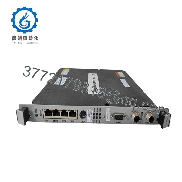
5466-1035
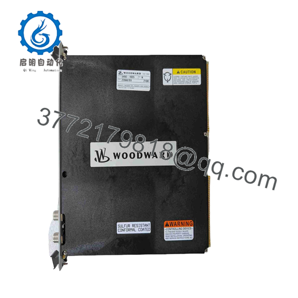
5466-1035
Frequently Asked Questions (FAQ)
What is the Woodward 5466-1035?
The 5466-1035 is a Woodward MicroNet high-density discrete I/O module used within MicroNet control systems. It provides discrete field I/O rather than acting as the main MicroNet CPU.
How many discrete I/O points does it provide?
The associated 5466-series high-density discrete architecture uses 48 discrete inputs and 24 discrete outputs. Verify the exact system documentation for the installed 5466-1035 revision before using this count for a wiring replacement.
Is the 5466-1035 obsolete?
The 5466-1035 belongs to the legacy Woodward MicroNet hardware family. For an installed legacy system, availability can depend heavily on surplus inventory. Confirm the exact hardware revision and physical condition before purchasing.
Can another 5466-series module replace the 5466-1035?
Not automatically. Similar-looking MicroNet I/O modules can have different electrical or software compatibility requirements. Check the CPU, Coder/software revision, FTM, I/O configuration, and system architecture before approving a substitute.
Does replacing the I/O module erase the MicroNet program?
The I/O module itself is not the primary location of the MicroNet control application. Replacing it therefore does not normally mean replacing the CPU application. However, you should still back up the control configuration before maintenance and verify I/O mapping after replacement.
Can the 5466-1035 be hot-swapped?
Do not assume hot-swap capability. Unless the specific MicroNet chassis and maintenance documentation explicitly authorize live replacement, isolate power before removing the module.
What should I verify before buying a surplus 5466-1035?
At minimum, request:
- Exact part number and hardware revision
- MicroNet CPU compatibility
- Software/Coder compatibility
- FTM compatibility
- Connector condition
- Input/output test results
- Physical condition
- New Original / New Surplus / Refurbished status
- Warranty and return terms
For a legacy MicroNet installation, the controller generation and software revision are just as important as the 5466-1035 part number.



