
 WhatsApp: +86 16626708626
 Email:
  Phone: +86 16626708626
Description
3. Key Technical Specifications
| Parameter | Value |
|---|---|
| Manufacturer | Woodward |
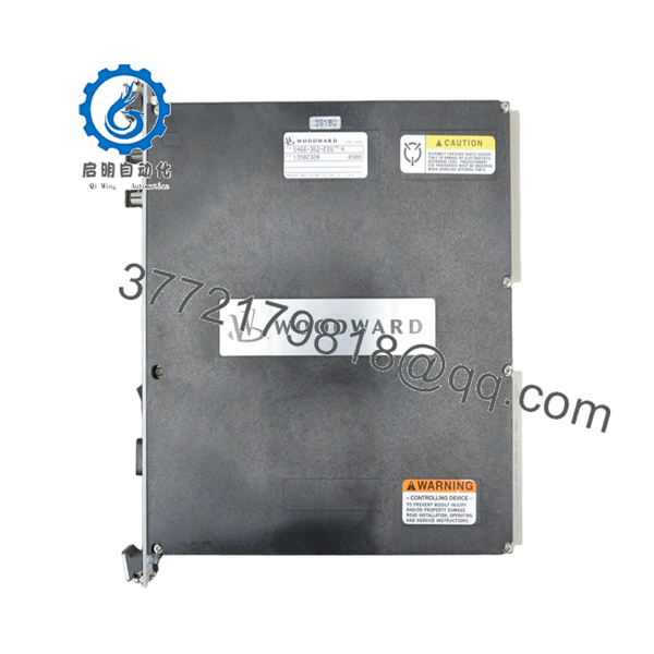
| Model Number | 5466-352-ESS |
| Product Type | NetCon CPU-040 CPU Module |
| Platform | Woodward MicroNet Control System |
| Processor | Motorola 68030 |
| System Architecture | VME Bus-Based Control Platform |
| Communication Method | Dual-Port RAM Communication |
| Network Processor Support | Up to 4 Network Communication Processors |
| CPU Type | CPU-040 Without LL Memory |
| Safety Function | IOLOCK Watchdog Protection |
| Installation Type | Rack/Chassis Mounted |
| Application | Turbine, Compressor, Engine Control |
| Country of Manufacture | USA |
| Status | Obsolete / Legacy Hardware |
Compatibility Note: The 5466-352-ESS was identified by Woodward as a NetCon CPU-040 module without LL memory and is part of the legacy MicroNet platform. CPU replacement frequently requires application software review, firmware validation, and in some cases chassis or I/O updates depending on system generation.
4. Product Introduction
The WOODWARD 5466-352-ESS is a NetCon CPU-040 processor module used within Woodward MicroNet turbine and compressor control systems. It serves as the primary control processor, handling application execution, network communication, watchdog supervision, and coordination between distributed I/O subsystems.
In operating power generation and rotating equipment installations, the CPU-040 platform is commonly found in long-life control systems where maintaining validated application software is often preferable to a complete controls migration. The ESS-tested version was supplied as a CPU assembly without LL memory and is now considered legacy hardware with limited availability.

- 5466-352-ESS
- 5466-352-ESS
5. Installation & Configuration Guide
Stage 1: Pre-Installation Preparation (10–15 Minutes)
⚠️ Safety First
- Notify operations and maintenance personnel of planned downtime.
- Place the turbine, compressor, or driven equipment into a verified safe shutdown condition.
- Apply lockout/tagout procedures.
- Isolate control power.
- Wait a minimum of 5 minutes for capacitor discharge.
Tools Required
- ESD wrist strap
- ESD grounding mat
- PH1 screwdriver
- Fluke 115 multimeter
- Label printer or wire tags
- Smartphone camera
- Flashlight
Data Backup
- Upload and archive current application software.
- Save controller configuration files.
- Record IP addresses and network settings.
- Photograph:
- CPU module label
- DIP switch settings
- Jumper locations
- Rack layout
- Fiber optic and communication connections
❗Before touching the CPU, verify that you actually have a usable backup. I’ve seen engineers discover corrupted backup files only after the old processor was already sitting on the workbench.
Stage 2: Removing the Old Module (5–10 Minutes)
- Open cabinet access panels.
- Identify the CPU module.
- Label every communication cable.
- Disconnect fiber optic and communication links carefully.
- Release retaining hardware.
- Pull the CPU straight out using even pressure.
⚠️ Do not twist the module.
MicroNet backplane connectors are expensive and difficult to source for older systems.
- Inspect:
- Backplane pins
- Chassis guides
- Dust accumulation
- Heat discoloration
- Connector damage
⚠️ Keep the original CPU available until startup is fully completed.
Stage 3: Installing the New Module (10 Minutes)
- Connect ESD wrist strap.
- Verify:
- Model number = 5466-352-ESS
- Correct CPU generation
- No shipping damage
Configuration Clone (Crucial)
- Match all switch settings.
- Match all jumper positions.
- Verify communication addressing.
- Verify watchdog and system configuration settings.
❗This is the most common rookie mistake, but it happens constantly. Take a picture before you pull it. I can’t stress this enough.
- Insert the replacement CPU into rack guides.
- Seat evenly until fully engaged.
- Tighten retaining hardware.
- Reconnect all communication cables.
Self-Checklist
- Part number matches
- Switches copied
- Jumpers copied
- Communication cables secured
- CPU fully seated
- Retaining hardware locked
Stage 4: Power-On & Testing (15–20 Minutes)
Pre-Power Check
- Measure control power voltage.
- Verify no shorts on power rails.
- Check cabinet grounding continuity.
Power-Up Procedure
- Energize the control rack only.
- Observe CPU startup LEDs.
- Verify boot sequence completes normally.
- Connect engineering workstation.
- Confirm:
- CPU detected
- Application recognized
- Communication healthy
- Firmware revision correct
- Verify watchdog status.
- Verify communication with all I/O racks.
- Perform dry-run testing before returning field devices to service.
⚠️ Troubleshooting Note
- Solid fault LED often indicates firmware mismatch.
- Communication failures frequently result from incorrect switch settings or incompatible software revisions.
- IOLOCK status usually points to processor startup or network communication faults.
Quality Control & Functional Verification SOP
1. Inbound Inspection & Traceability
Each 5466-352-ESS module undergoes:
- OEM identification verification.
- Serial number recording.
- Anti-counterfeit label inspection.
- Visual inspection under magnification.
Inspection criteria:
- No corrosion
- No damaged connectors
- No PCB rework marks
- No UV discoloration
- No physical damage
Accessory verification includes:
- Factory labels
- Original packaging when available
- Documentation and certificates
2. Live Functional Testing
Testing is performed on a Woodward-compatible MicroNet simulation rack.
Verification includes:
- Power-on self-test.
- LED sequence validation.
- VME communication verification.
- CPU boot testing.
- Communication processor handshake testing.
- 24-hour continuous runtime test.
- Thermal monitoring under load.
Official test reports are generated for tested inventory.
Test photos and startup videos are available upon request.
3. Electrical Parameter Testing
Testing includes:
- 500 V insulation resistance testing
- Ground continuity verification
- Power rail verification
- Hipot testing where applicable
Acceptance target:
- Greater than 10 MΩ insulation resistance
4. Firmware & Configuration Verification
- Firmware revision documented.
- Hardware revision archived.
- Configuration settings recorded.
- DIP switch positions photographed.
5. Final QC & Packaging
- QC inspector approval.
- ESD-safe packaging.
- Anti-static bag sealing.
- Multi-layer protective wrap.
- Heavy-duty export carton.
- QC Passed label with inspection date.
Common Replacement Pitfalls From Field Experience
❗ Firmware Revision Mismatch
This is the fastest way to turn a one-hour shutdown into a two-day outage.
I’ve seen technicians replace a CPU-040 with a newer processor revision and immediately lose communication to multiple network processors. The hardware wasn’t defective. The software versions didn’t match.
Avoidance:
- Document firmware before removal.
- Request firmware verification before shipment.
- Validate compatibility with installed application software.
❗ DIP Switch and Jumper Errors
A single incorrect switch can prevent startup.
One incorrect address setting can make the CPU invisible to the rest of the system.
Avoidance:
- Photograph everything.
- Verify switch positions twice.
- Compare against existing drawings.
❗ Fiber Optic and Communication Connections
The CPU-040 platform relies heavily on network communications.
I’ve seen maintenance teams spend hours troubleshooting what turned out to be a reversed fiber pair.
Avoidance:
- Label cables before removal.
- Inspect fiber ends.
- Verify communication path integrity.
❗ Power Supply Loading
Legacy MicroNet installations often operate with little power margin remaining.
Adding newer hardware revisions can expose marginal power supplies.
Avoidance:
- Measure voltage under load.
- Maintain at least 20% spare capacity.
- Verify power supply condition before startup.
❗ Electrostatic Discharge (ESD)
CPU modules are particularly vulnerable during handling.
I watched a contractor remove a processor during winter without grounding himself. The replacement never completed boot-up. Expensive lesson.
Avoidance:
- Ground strap.
- ESD mat.
- Anti-static handling procedures.
Keep these checks in mind and you’ll save yourself 90% of typical rework time.
6. Frequently Asked Questions (FAQ)
Q1: Can I hot-swap the WOODWARD 5466-352-ESS?
No.
This CPU module should be treated as non-hot-swappable. Removing it under power can trigger IOLOCK conditions, communication failures, or backplane damage. Always shut down the control rack first.
Q2: Is the 5466-352-ESS obsolete?
Yes.
Woodward listed the 5466-352-ESS as an obsolete NetCon CPU-040 assembly. Last-time-buy notices were issued as part of MicroNet CPU platform migration programs.
Q3: What does ESS mean in 5466-352-ESS?
According to Woodward obsolescence documentation, the 5466-352-ESS version is identified as a CPU-040 module without LL memory and supplied as an ESS-tested assembly. Exact project-specific configuration should still be verified against OEM documentation.
Q4: Will replacing this CPU erase my application software?
Potentially.
Unlike simple I/O modules, this is the control processor itself.
Before replacement:
- Upload the application.
- Archive configuration files.
- Verify recovery procedures.
- Confirm firmware compatibility.
Never assume the replacement CPU contains the correct application.
Q5: What is the direct replacement for 5466-352-ESS?
There is no universal drop-in replacement.
Woodward’s migration notices indicate that CPU upgrades may require:
- Application software updates
- Chassis replacement
- Power supply replacement
- I/O compatibility review
Replacement planning should be performed at the system level, not just the module level.
Q6: Why are surplus units significantly cheaper than OEM migration projects?
Because you’re buying hardware only.
OEM upgrade projects often include:
- Engineering review
- Software conversion
- Startup support
- Validation testing
- Warranty programs
Surplus inventory generally provides the hardware without those engineering services.
Q7: What information should I provide before ordering?
Send:
- CPU label photo
- Complete part number
- Firmware revision
- Chassis photo
- System architecture (Simplex, Redundant, or TMR)
- Existing software version
That information prevents most compatibility mistakes before the replacement arrives on-site.


