
 WhatsApp: +86 16626708626
 Email:
  Phone: +86 16626708626
Description
3. Key Technical Specifications
| Parameter | Value |
|---|---|
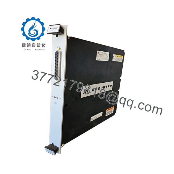
| Manufacturer | Woodward |
| Model Number | 5466-5003 |
| Product Type | Speed Sensor Input Module |
| Platform | MicroNet / MicroNet Plus |
| Architecture | Smart-Plus |
| Input Channels | 4 Speed Channels |
| Sensor Configuration | 3 MPU Channels + 1 Proximity Probe Channel |
| Application | Turbine, Compressor, Engine Speed Monitoring |
| Communication | MicroNet Backplane |
| Installation | Rack-Mounted Module |
| Controller Compatibility | MicroNet Plus, CPU5200 Platforms |
| Required Coder Version | 4.06 or Later |
| System Types | Simplex and Redundant Systems |
| Country of Origin | USA |
| Status | Active Smart-Plus Platform |
Woodward identifies the 5466-5003 as a MicroNet Speed Sensor, 4 Channel, 3 MPU / 1 Proximity Smart-Plus module. It was introduced as the replacement for the legacy 5464-850 speed sensing module and requires Coder Version 4.06 or later.
4. Product Introduction
The WOODWARD 5466-5003 is a Smart-Plus speed sensor module designed for MicroNet and MicroNet Plus control systems. The module processes four independent speed inputs using three magnetic pickup (MPU) channels and one proximity probe channel, making it suitable for gas turbines, steam turbines, compressors, and critical rotating machinery.
In field upgrades, the 5466-5003 is commonly selected when replacing older 5464-850 speed input modules because it maintains application compatibility while providing improved Smart-Plus diagnostics and speed processing capabilities. For retrofit projects, verify Coder version compatibility before installation.

- 5466-5003
5. Installation & Configuration Guide
Stage 1: Pre-Installation Preparation (10–15 Minutes)
⚠️ Safety First
- Notify operations personnel of the planned outage.
- Bring the turbine or driven equipment to a safe shutdown condition.
- Apply lockout/tagout procedures.
- Isolate all control power.
- Wait a minimum of 5 minutes before opening the cabinet.
Tools Required
- ESD wrist strap
- ESD work mat
- PH1 screwdriver
- Fluke 115 multimeter
- Wire markers
- Smartphone camera
- Flashlight
Data Backup
- Archive current application files.
- Save controller configuration.
- Record network settings.
- Photograph:
- Existing module label
- Terminal wiring
- Rack location
- DIP switches
- Sensor wiring terminations
❗Speed sensing modules often support critical overspeed functions. Verify documentation before disconnecting any field wiring.
Stage 2: Removing the Old Module (5–10 Minutes)
- Open the control cabinet.
- Locate the speed sensor module.
- Label all field cables.
- Disconnect sensor wiring carefully.
- Remove retaining hardware.
- Pull the module straight out.
⚠️ Do not twist the card while removing it.
Older MicroNet backplane connectors can be damaged if excessive force is applied.
- Inspect:
- Backplane pins
- Connector condition
- Dust accumulation
- Heat discoloration
⚠️ Keep the original module available until startup is completed successfully.
Stage 3: Installing the New Module (10 Minutes)
- Wear a grounded ESD wrist strap.
- Verify:
- Part Number = 5466-5003
- Correct hardware revision
- No physical damage
Configuration Clone (Crucial)
- Compare switch settings.
- Verify sensor channel assignments.
- Confirm MPU and proximity probe wiring locations.
- Verify shielding and grounding arrangements.
❗This is the most common rookie mistake, but it happens constantly. Take a picture before you pull it. I can’t stress this enough.
- Insert module into rack guides.
- Seat fully into the backplane.
- Secure retaining hardware.
- Reconnect field wiring.
Self-Checklist
- Model verified
- Wiring restored
- Shielding verified
- Module fully seated
- Retaining hardware secured
- Channel assignments confirmed
Stage 4: Power-On & Testing (15 Minutes)
Pre-Power Check
- Verify no shorts on control power.
- Check cabinet grounding continuity.
- Confirm sensor wiring integrity.
Power-Up Procedure
- Energize the control rack.
- Observe LED startup sequence.
- Connect engineering workstation.
- Verify:
- Module detected
- Speed channels online
- No communication faults
- Correct module identification
- Simulate or verify actual speed signals.
- Confirm proper speed indication.
- Validate overspeed and alarm functions where permitted.
⚠️ Troubleshooting Note
- Red fault LED typically indicates configuration or firmware issues.
- Missing speed signals often result from incorrect MPU polarity or wiring.
- Unstable readings usually point to grounding or shielding problems.
Quality Control & Functional Verification SOP
1. Inbound Inspection & Traceability
Each 5466-5003 module undergoes:
- OEM identification verification.
- Serial number recording.
- Anti-counterfeit inspection.
- Visual examination.
Inspection criteria:
- No corrosion
- No connector damage
- No rework marks
- No UV discoloration
- No damaged PCB traces
Accessory audit includes:
- Factory labels
- Packaging
- Documentation when available
2. Live Functional Testing
Testing is performed using a MicroNet-compatible Smart-Plus test rack.
Procedures include:
- Power-on self-test.
- LED verification.
- Backplane communication testing.
- Simulated MPU input testing.
- Simulated proximity probe testing.
- Continuous operation exceeding 24 hours.
- Thermal monitoring under load.
An official test report is generated.
Test videos and photos are available upon request.
3. Electrical Parameter Testing
Testing includes:
- 500 V Megger insulation resistance test
- Ground continuity verification
- Power rail measurements
- Hipot testing where applicable
Acceptance criteria:
- Greater than 10 MΩ insulation resistance
4. Firmware & Configuration Verification
- Firmware revision documented.
- Hardware revision recorded.
- Configuration settings archived.
- Switch settings photographed.
5. Final QC & Packaging
- QC sign-off.
- ESD-safe packaging.
- Anti-static bag sealing.
- Protective bubble wrapping.
- Heavy-duty export carton.
- QC Passed label with inspection date.
Common Replacement Pitfalls From Field Experience
❗ Firmware Revision Mismatch
The 5466-5003 requires appropriate MicroNet software support.
I’ve seen a startup delayed nearly two shifts because the hardware was installed correctly, but the controller was running an older Coder revision that couldn’t properly recognize the Smart-Plus module.
Avoidance:
- Verify Coder version before ordering.
- Confirm compatibility with installed CPU firmware.
- Record existing software revisions.
❗ Incorrect Sensor Assignment
This is extremely common.
One maintenance team connected the proximity probe to an MPU-designated channel. The module stayed healthy, but the speed indication was completely wrong.
Avoidance:
- Verify sensor type per channel.
- Label wiring before removal.
- Check startup diagnostics carefully.
❗ Wiring and Shield Grounding Errors
Speed inputs are sensitive to electrical noise.
I’ve watched technicians replace a perfectly good module when the real problem was a floating cable shield.
Avoidance:
- Follow Woodward grounding recommendations.
- Inspect cable shielding.
- Verify shield termination points.
❗ Power Supply Margin
Control power problems frequently masquerade as speed sensing faults.
Avoidance:
- Verify supply voltage under load.
- Maintain at least 20% power reserve.
- Check power supply health before startup.
❗ Electrostatic Discharge (ESD)
Speed sensing electronics are vulnerable to static discharge.
I once watched a replacement module fail immediately after installation because it was handled without ESD protection during a dry winter outage.
Avoidance:
- Grounded wrist strap.
- ESD mat.
- Anti-static packaging until installation.
Keep these checks in mind and you’ll save yourself 90% of typical rework time.
6. Frequently Asked Questions (FAQ)
Q1: What sensors does the 5466-5003 support?
The module supports:
- 3 Magnetic Pickup (MPU) channels
- 1 Proximity Probe channel
This configuration was specifically introduced as the replacement for the legacy 5464-850 module.
Q2: Is the 5466-5003 a direct replacement for 5464-850?
Generally yes.
Woodward identifies the 5466-5003 as the replacement for the 5464-850 speed sensor module. However, verify software compatibility and Coder version requirements before installation.
Q3: What software version is required?
Woodward specifies Coder Version 4.06 or later for operation with the Smart-Plus speed sensor family.
Q4: Can I hot-swap the 5466-5003?
That depends on the specific MicroNet architecture and site procedures.
For critical turbine control systems, I generally recommend a planned shutdown unless the operating philosophy and OEM documentation explicitly permit online replacement.
Q5: Will replacing this module erase my application logic?
No.
The 5466-5003 is an I/O speed sensing module. Application logic remains in the controller CPU.
Even so, always create a complete backup before maintenance.
Q6: Is this module obsolete?
No. Unlike many earlier MicroNet speed input modules, the 5466-5003 belongs to the Smart-Plus family introduced to replace older legacy speed sensor modules. It remains part of Woodward’s updated MicroNet architecture.
Q7: What information should I provide before requesting a quote?
Provide:
- Existing module photo
- Controller model
- Coder software version
- Chassis type
- Sensor type (MPU or proximity)
- System architecture (Simplex, Redundant, or TMR)
Those six items eliminate most compatibility problems before shipment and reduce startup risk during installation.


