
 WhatsApp: +86 16626708626
 Email:
  Phone: +86 16626708626
Description
Key Technical Specifications
- Product Type: TMR Power Supply Unit for the MicroNet control platform
- Input Voltage: 220 VAC
- Maximum Input Power: 1,250 VA
- Overcurrent Protection: 10 A time-delay input breaker/fuse
- Chassis Requirement: Mounts in the MicroNet TMR power supply chassis
- Redundancy Configuration: Up to two supply boards per redundant pair, housed in separate chassis and interconnected via ribbon cabling
- Serviceability: Reported as hot-swappable, provided the redundant supply partner remains active during replacement
- Status Indication: Front-panel LEDs reported for fault and normal-operation status
⚠️ Fair warning on this part number: search results for the 5501-381 are unusually scattered. Multiple distributor pages describe completely different hardware under this same number — a 24 VDC/100 W DIN-rail supply, a compact PLC/motion-control unit, and a generic “digital processor” with an unrelated feature list. None of that matches the MicroNet TMR power supply description that the more detailed listings converge on. Don’t spec a replacement, wiring, or a chassis slot off any single distributor page — pull Woodward’s own MicroNet TMR power supply documentation and confirm the exact hardware revision before you order or install this.
Product Introduction
The Woodward 5501-381 is a Triple Modular Redundant power supply board built for the MicroNet TMR control platform, converting a 220 VAC input into the regulated DC rails a MicroNet TMR chassis needs. It’s designed to run in a redundant pair — two boards, housed in separate chassis, tied together with ribbon cabling — so a single supply fault doesn’t take the control system down.
Plants running MicroNet TMR racks keep this on hand because a redundant power supply failure is exactly the kind of fault that’s supposed to be non-disruptive, provided the partner supply is confirmed healthy and the replacement gets done correctly.
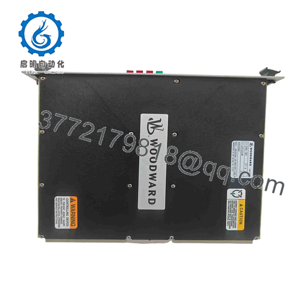
5501-381
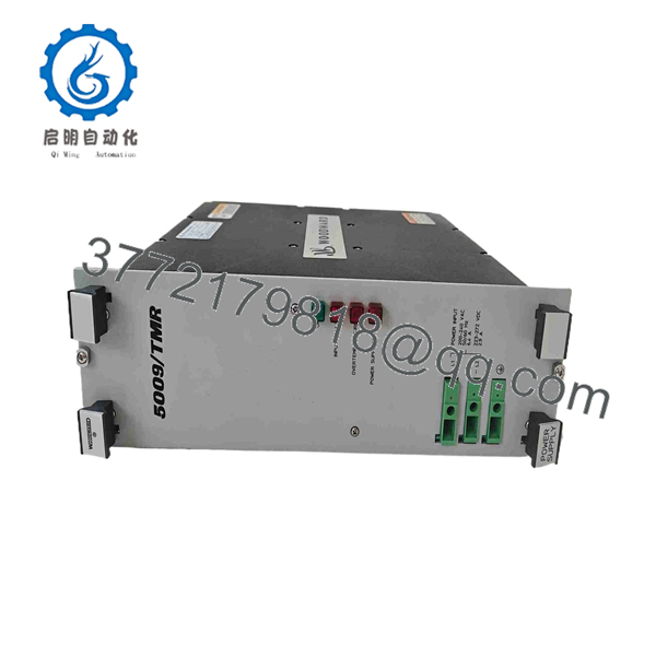
5501-381
Troubleshooting Quick Reference
| Symptom | Possible Cause | Relevance to this Part | Quick Check Method | Recommendation |
|---|---|---|---|---|
| Fault LED lit on one supply board, chassis still running | Redundant partner is carrying the load — this is the designed failover behavior | ✅ High | Confirm the partner supply’s LED shows normal/OK status | Replace the faulted board while the partner carries the load; don’t wait for both to fail |
| Both supply boards showing fault, chassis lost power | Upstream 220 VAC feed lost, or the 10 A input breaker tripped on both boards | ✅ High | Measure incoming 220 VAC at the chassis input terminals; check breaker status on both boards | Restore the upstream supply and check for the fault that tripped both breakers before replacing hardware |
| Board won’t power up during hot-swap replacement | Ribbon cable interconnect not seated correctly between chassis, or board not fully seated in its slot | ⚠️ Medium | Reseat the ribbon cable and confirm the board is fully inserted and latched | Correct the connection before assuming the board itself is bad |
| Overtemperature indication | Blocked chassis ventilation or ambient temperature exceeding rating | ⚠️ Medium | Check chassis airflow and ambient temperature around the power supply enclosure | Fix cooling before replacing the board — the protection is doing its job |
| Nuisance breaker trips on one board under normal load | Input breaker degraded with age, or a marginal downstream load fault | ⚠️ Medium | Monitor breaker trip pattern and check downstream DC rail loading | If trips recur with no load change, treat as a board-level fault |
If these checks don’t isolate the issue, contact technical support with both boards’ LED status and the exact hardware revision printed on the board before ordering a replacement.
Frequently Asked Questions (FAQ)
Can I really hot-swap this while the control system is running?
Reported as yes, but only with the redundant partner supply confirmed active and healthy. Never pull a board based on assumption alone — verify the partner’s status LED first. This is a control system power supply, not something to gamble on.
Do I need two of these, or does one board run the whole chassis?
For redundant operation, Woodward’s TMR architecture calls for a pair — one in each of two separate chassis, linked by ribbon cable. Running a single board loses the redundancy the design is built around, so confirm your system’s actual configuration before assuming a single unit covers you.
Is this a direct drop-in replacement for the board I’m pulling?
Given how inconsistent online listings are for this part number, confirm the exact hardware revision against Woodward’s documentation rather than trusting a distributor’s spec sheet. A mismatch on a power supply board is not something you want to discover after installation.
What input voltage does this actually run on?
The best-corroborated listings point to 220 VAC. If a seller quotes you 24 VDC or another voltage for this same part number, ask them to confirm the exact hardware revision — that mismatch is a sign the listing may not describe the same board.
Why do I see such different descriptions of this part across different sites?
Frankly, this is one of the messier part numbers to research — several listings appear to describe unrelated Woodward products under the same number. Treat any online spec sheet as a starting point and confirm against Woodward’s own MicroNet TMR documentation before you commit.
What condition should I expect on a surplus unit?
Ask directly whether it’s unused surplus stock or a tested/rebuilt exchange unit. For a power supply feeding a redundant control chassis, knowing whether it was actually load-tested before shipping matters more than the price difference.
What warranty applies?
Terms vary by seller — some quote a standard one-year warranty, others offer extended coverage on rebuilt units. Get the specific terms in writing, and factor in that sourcing a second replacement for a part this specialized may take longer than expected if this one doesn’t work out.



