
 WhatsApp: +86 16626708626
 Email:
  Phone: +86 16626708626
Description
Key Technical Specifications
| Parameter | Value |
|---|---|
| Manufacturer | Woodward |
| Model | 8290-185 |
| Product Family | EPG Electrically Powered Governor |
| Product Type | Isochronous Speed Control |
| Engine Application | Gasoline or natural gas engine |
| System Voltage | 24 VDC |
| Speed Range | 3,000–6,000 Hz |
| Actuator Compatibility | 524 / 1724 |
| Actuator Type | Electrically powered governor actuator |
| Control Mode | Isochronous |
| Start Fuel Limit | Included |
| Magnetic Pickup Minimum | 1.5 Vrms |
| Maximum Power Consumption | 95 W |
| Ambient Temperature | −40 to +75 °C |
| Battery Charger Capability | 5 A |
| Compliance | EU Directive / CE |
| Related Manual | Woodward Manual 82493 |
| Related Specification | Woodward Specification 04106 |
Woodward’s official Specification 04106 identifies 8290-185 as an EPG isochronous speed control for gasoline or gas engines, 24 V, with a 3,000–6,000 Hz speed range. Woodward’s Manual 82493 places the 8290-185 in the 24 V gasoline/gas-engine category with a start-fuel-limit configuration and 524/1724 actuator compatibility.
The 8290-185 is not a general-purpose PLC speed controller. It is part of a dedicated EPG governing system, which uses an electronic speed control, actuator, and magnetic pickup. The actuator linkage and direction must match the engine’s fuel-control mechanism.
Product Introduction
The Woodward 8290-185 is a 24 VDC EPG isochronous speed control designed for gasoline or natural-gas prime movers using Woodward 524 or 1724 actuators. Its specified speed-sensing range is 3,000–6,000 Hz, and the controller includes a start-fuel-limit function.
This controller belongs to a three-component EPG system consisting of the electronic speed control, actuator, and magnetic pickup. Replacement therefore requires more than matching the controller part number; the pickup frequency, actuator, linkage direction, and engine fuel-control characteristics must also be verified.
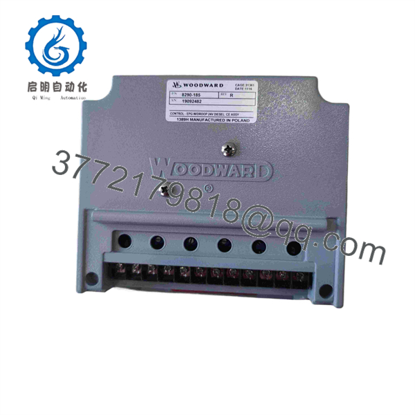
8290-185
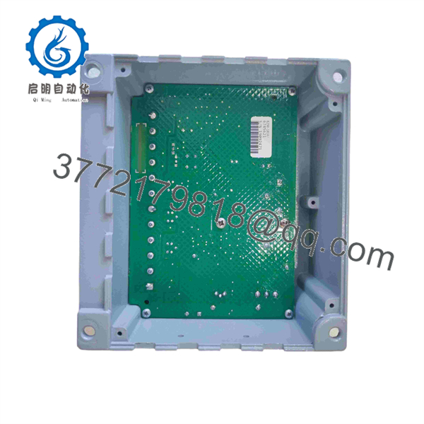
8290-185
Installation & Configuration Guide
Stage 1: Pre-Installation Preparation
Estimated time: 20–30 minutes
- Notify operations and place the engine or generator in its approved maintenance state.
- Follow the engine manufacturer’s shutdown and LOTO procedure.
- Isolate the 24 VDC governor supply.
- Prevent unintended engine starting before disconnecting the controller.
- Wait at least 5 minutes after power isolation before handling the controller.
- Wear an ESD wrist strap.
- Prepare:
- Digital multimeter
- PH1 screwdriver
- Wire labels
- Camera/phone
- Woodward Manual 82493
- Existing governor wiring diagram
- Existing speed-control settings
- Photograph the controller, terminals, actuator linkage, and magnetic-pickup wiring.
- Record the existing controller part number and revision.
- Record the magnetic-pickup frequency range and actuator model.
⚠️ The 8290-185 is part of an engine governing system. A wiring mistake can cause incorrect fuel positioning or prevent the engine from reaching the commanded speed.
Stage 2: Removing the Old Module
Estimated time: 15–25 minutes
- Confirm the engine is secured against unintended starting.
- Verify the 24 VDC supply is isolated.
- Label every controller connection.
- Photograph terminal positions before disconnecting wires.
- Identify the magnetic-pickup input.
- Identify actuator output connections.
- Disconnect any auxiliary or ramp-generator connections if installed.
- Remove wiring without pulling on individual conductors.
- Remove the controller mounting hardware.
- Remove the existing speed-control unit.
- Inspect terminals and wiring for corrosion, loose connections, damaged insulation, or poor shielding.
- Keep the original controller until commissioning is complete.
⚠️ Do not assume that the magnetic-pickup signal is correct because the engine previously ran. Verify the pickup wiring and signal level during replacement.
Stage 3: Installing the New Module
Estimated time: 20–30 minutes
- Confirm the replacement is marked Woodward 8290-185.
- Verify the application is 24 V gasoline/gas engine service.
- Confirm the required operating speed corresponds to the 3,000–6,000 Hz control range.
- Secure the controller in its approved location.
- Reconnect the 24 VDC supply.
- Reconnect the magnetic pickup.
- Reconnect the 524 or 1724 actuator circuit.
- Verify actuator polarity and wiring.
- Confirm any optional ramp-generator wiring.
- Check all terminal assignments against the Woodward wiring diagram.
- Check supply polarity and continuity before energizing.
Configuration Check — Critical
- Verify the magnetic-pickup frequency.
- Verify rated engine speed.
- Verify actuator model.
- Verify actuator direction.
- Verify fuel-control linkage geometry.
- Verify the start-fuel-limit setting.
- Verify any optional ramp-generator configuration.
- Verify any load-control accessories installed with the governor.
Woodward specifically notes that the actuator linkage must provide the required relationship between actuator movement and fuel-control movement, including the correct direction for increased fuel.
Stage 4: Power-On & Testing
Estimated time: 45–90 minutes
- Confirm the engine is in a safe condition for controlled testing.
- Verify the 24 VDC supply voltage.
- Energize the 8290-185.
- Verify the controller’s operating condition.
- Confirm the magnetic pickup produces the expected signal.
- Verify speed feedback against an independent reference where available.
- Start the engine according to the approved startup procedure.
- Verify stable speed regulation at no-load.
- Check actuator response and direction.
- Increase load in controlled steps.
- Verify that engine speed remains within the required operating band.
- Check for hunting, excessive actuator movement, or abnormal fuel response.
- Verify any installed ramp-generator or load-control functions.
- Record final operating parameters.
⚠️ Do not tune the actuator by changing multiple parameters simultaneously. Establish correct pickup feedback and actuator direction first, then adjust governing parameters systematically.
Woodward’s installation documentation also states that the 524/1724 actuator must be located so the required linkage can be established and that linkage linearity must match the engine’s fuel-control requirements.
Frequently Asked Questions (FAQ)
1. What is the Woodward 8290-185?
The 8290-185 is a Woodward EPG Electrically Powered Governor isochronous speed control for 24 V gasoline or natural-gas engine applications. Woodward specifies it for use with the 524 and 1724 actuators.
2. What voltage does the 8290-185 require?
The 8290-185 is a 24 VDC control. Woodward’s EPG documentation places it in the 24 V gasoline/gas-engine category. Secondary technical references report a 24 V system supply and maximum power consumption of approximately 95 W.
3. What engines can use the 8290-185?
It is specified for gasoline or natural-gas engines. It is not the correct choice simply because an engine uses a 24 V electrical system; the engine type, required speed-sensing range, actuator, and fuel-control linkage must also match.
4. Which actuators are compatible with 8290-185?
Woodward identifies the 524 and 1724 actuator families for this EPG configuration. The actuator linkage must also match the engine fuel-control mechanism and required direction of movement.
5. What magnetic-pickup signal does the 8290-185 require?
The 8290-185 is associated with a 3,000–6,000 Hz speed range. Secondary technical documentation specifies a minimum magnetic-pickup signal of 1.5 Vrms. Verify the actual pickup output under operating conditions before commissioning.
6. Does the 8290-185 include a start-fuel limit?
Yes. Woodward’s EPG part-number table identifies 8290-185 as the 24 V gasoline/gas configuration with start fuel limit.
7. Is the Woodward 8290-185 still available?
The original Woodward EPG product line has changed ownership. QCC currently lists 8290-185 as an EPG controller formerly manufactured under Woodward and identifies it as “CONTROL – EPG SPEED 24V GAS (CE) ASSY.” QCC also lists Cummins 4948661 as a crossover part number. For procurement, verify whether the offered unit is original Woodward stock, later production, new surplus, or refurbished.



