
 WhatsApp: +86 16626708626
 Email:
  Phone: +86 16626708626
Description
Key Technical Specifications
| Parameter | Value |
|---|---|
| Manufacturer | XP Power |
| Model | F8B6D4A3G3 |
| Series | F8 Series |
| Product Type | AC-DC chassis mount power supply |
| Output Power | 1,200 W |
| Output Voltage | 24 VDC |
| Output Current | 50 A |
| Input Voltage Range | 90–264 VAC |
| Input Frequency | 47–63 Hz |
| Cooling Method | Conduction cooled / chassis mounted |
| Efficiency | Up to approximately 94% |
| Output Configuration | Single output |
| Protection Functions | Over voltage, over current, short circuit, over temperature protection |
| Power Factor Correction | Active PFC |
| Operating Temperature | Verify exact derating curve from OEM datasheet before installation |
| Application Category | Industrial equipment, automation systems, power distribution |
| Mounting Style | Enclosed chassis mount |
| Safety Standards | Verify applicable certification requirements for final equipment integration |
Product Introduction
The XP Power F8B6D4A3G3 is an F8 Series AC-DC power supply designed to provide a regulated 24 VDC, 50 A output for industrial and equipment power applications. It converts universal AC input voltage from 90–264 VAC into a high-current DC supply suitable for control cabinets, automation equipment, and electronic systems.
This model is selected in applications requiring a high-power 24 VDC source with active PFC and chassis mounting. When replacing an existing unit, engineers should verify mechanical dimensions, output wiring, thermal installation method, and load requirements against the OEM documentation.
Installation & Configuration Guide
Stage 1: Pre-Installation Preparation (Approx. 15 minutes)
⚠️ Safety First
- Notify production and maintenance teams before removing the power supply.
- Confirm the connected automation system can enter a safe shutdown condition.
- Apply lockout/tagout procedures to the AC input source.
- Wait at least 5 minutes for internal capacitors to discharge.
- Confirm zero voltage before touching terminals.
Tools Required
- ESD wrist strap
- PH1/PH2 screwdriver
- Digital multimeter
- Wire labels
- Smartphone or camera for wiring photos
- Torque screwdriver if specified by cabinet documentation
Data Backup
Before removing the existing power supply:
- Record the original XP Power model number and revision label.
- Photograph:
- AC input wiring
- DC output terminals
- Remote sense wiring (if used)
- Ground connection
- Mounting orientation
- Measure existing output voltage at the load side.
- Record the connected load current if available.
Stage 2: Removing the Old Module (Approx. 10 minutes)
- Remove cabinet covers and ensure the work area is free from loose conductive material.
- Label all AC and DC conductors before disconnecting.
- Disconnect input and output wiring carefully.
- Remove mounting screws or brackets.
- Lift the power supply away from the mounting surface.
⚠️ Note: Keep the original unit until the replacement has completed startup testing. Terminal location and grounding details are valuable references.
Stage 3: Installing the New Module (Approx. 15 minutes)
- Wear an ESD strap before handling the replacement unit.
- Verify:
- Model: XP Power F8B6D4A3G3
- Output: 24 VDC, 50 A
- Power Rating: 1,200 W
⚠️ Configuration Clone — Critical Step
- Replicate the original installation:
- AC line connection
- Neutral connection
- Protective earth connection
- DC positive and negative wiring
- Remote sensing connections if applicable
- Mount the supply securely against the approved chassis surface.
- Verify thermal conditions:
- Mounting surface provides required heat dissipation.
- Cabinet airflow matches the original design.
- Ambient temperature remains within the OEM operating limits.
Self-Checklist
- Input wiring verified
- Output polarity confirmed
- Ground connection secured
- Mounting hardware tightened
- Cooling requirements checked
Stage 4: Power-On & Testing (Approx. 15 minutes)
Pre-Power Check
- Measure resistance between DC output terminals and chassis ground.
- Verify no wiring short exists.
- Confirm AC input voltage is within specification.
Power-On Steps
- Energize AC input only.
- Measure DC output voltage without load.
- Connect the downstream DC load.
- Monitor:
- Output voltage stability
- Current draw
- Temperature rise
- Run the connected control system for functional verification.
⚠️ Troubleshooting Note
- Low output voltage: Check load current, wiring resistance, and terminal torque.
- Shutdown under load: Check thermal installation and current demand.
- No output: Verify AC input, protection state, and wiring polarity.
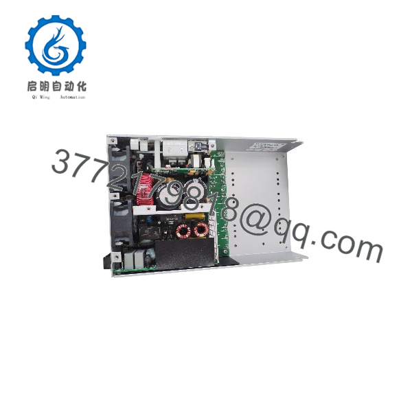
F8B6D4A3G3
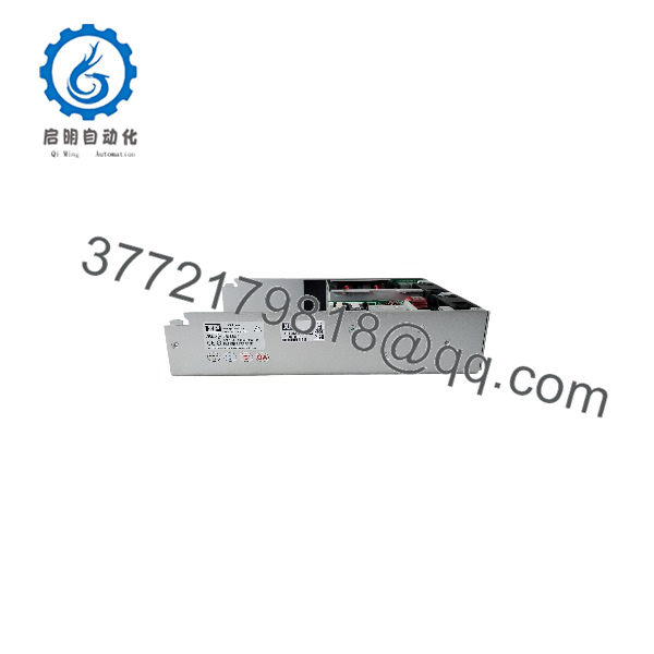
F8B6D4A3G3
Frequently Asked Questions (FAQ)
Can the XP Power F8B6D4A3G3 be hot-swapped under power?
No. This power supply is not intended for hot replacement. Disconnect AC input power before removal. Working on a live 1,200 W power supply creates electrical safety risks and can damage connected equipment.
Is the F8B6D4A3G3 obsolete, and is it still available?
The F8B6D4A3G3 is a legacy XP Power model. Availability depends on remaining inventory channels because it is no longer a commonly stocked current production item. New Original / New Surplus units are typically sourced from industrial inventory holdings.
Can I replace a lower-power 24 VDC supply with the ?
Usually, yes, if the electrical specifications match and the physical installation is suitable. A higher wattage rating does not force more current into the load; the equipment draws only the current it requires. However, verify wiring size, circuit protection, and cabinet thermal design before installation.
What should I check before ordering this XP Power model?
Confirm:
- Exact model number:
- Output requirement: 24 VDC
- Required load current
- AC input voltage range
- Mounting dimensions
- Terminal arrangement
- Cooling method
Do not order only by output voltage. Power supplies with similar voltage ratings may have different wiring, protection, and mechanical requirements.
Why is this unit priced differently from a new OEM supply?
Industrial power supply pricing varies based on production status, inventory condition, certification requirements, and availability. New Surplus units may come from unused inventory rather than current factory production. Always verify condition documentation before installation.
Does replacing the require PLC program changes?
No. The power supply does not store PLC logic or configuration data. However, after replacement, verify that the 24 VDC bus voltage is stable because PLC CPUs, remote I/O, sensors, and communication devices depend on proper DC power quality.
What inspection should be completed before installing a surplus ?
A professional incoming inspection should include:
- Serial number and label verification.
- Visual inspection for corrosion, impact damage, or rework marks.
- Insulation and grounding checks.
- Output voltage test under load.
- Thermal monitoring during extended operation.
- Documentation of test results.
Test photos and inspection records should be available upon request for traceability.



