
 WhatsApp: +86 16626708626
 Email:
  Phone: +86 16626708626
Description
Key Technical Specifications
- Part Number: CPS-150F
- Manufacturer: Yaskawa Electric
- Product Category: Controller power supply module
- Primary Application: Motoman XRC and NX100 robot controller cabinets
- Input Voltage: 200–230 V AC
- Input Frequency: 50/60 Hz
- Input Current: 2.1 A
- Nominal Input Apparent Power: Approximately 483 VA maximum, calculated from 230 V × 2.1 A
- Approximate Dimensions: 180 mm H × 60 mm W × 270 mm L
- Installation Location: Original Yaskawa controller power-supply position; not a general-purpose DIN-rail supply
- Controller Compatibility: Confirm against the controller wiring diagram and the label on the removed unit
- Service Condition: Replacement should match the existing CPS-150F part number exactly; do not assume third-party 24 V DC supplies are electrically or mechanically interchangeable.
Product Introduction
The Yaskawa CPS-150F is an industrial power supply module used in Motoman XRC and NX100 robot controllers. It accepts 200–230 V AC at 50/60 Hz and supplies internal controller power through the controller’s designated wiring and connector arrangement.
Plants normally replace this unit to restore an existing controller, not to upgrade a robot system. The practical selection criterion is exact part-number matching, connector condition, input-voltage compatibility, and confirmation that the controller does not have an upstream fuse, transformer, or contactor fault.
Installation & Configuration Guide
Stage 1: Pre-Installation Preparation — 10 minutes
⚠️ Safety First: Notify operations, place the robot cell in a safe state, apply lockout/tagout to the controller incoming supply, and verify absence of voltage before opening the cabinet. Wait at least 5 minutes for internal DC-bus and filter capacitors to discharge.
Tools required:
- Grounded ESD wrist strap and ESD-safe work surface
- PH1 screwdriver
- CAT-rated multimeter
- Wire labels or masking labels
- Smartphone for high-resolution photos
- Torque screwdriver if the controller documentation specifies terminal torque
- Export or back up the controller job, parameters, alarms, and system configuration if the controller remains operational.
- Photograph the CPS-150F from all sides before touching any wiring.
- Record incoming voltage, protective-earth connection, fuse ratings, connector identifiers, and every terminal marking.
- Check the replacement label carefully: it must read Yaskawa CPS-150F. Do not substitute a similarly sized power supply without reviewing the XRC or NX100 electrical drawings.
- Measure the incoming supply at the isolation point. The existing unit requires 200–230 V AC service; a 380–480 V feed must pass through the correct transformer or power-conditioning arrangement before reaching this module.
Stage 2: Removing the Old Module — 5 minutes
- Remove the controller front cover or internal protective panel as required by the specific XRC or NX100 cabinet design.
- Confirm with a multimeter that the supply conductors are de-energized.
- Label every wire and connector before removal. Include protective earth, AC input conductors, and all low-voltage output plugs.
- Disconnect plugs by their housings. Do not pull on wires or force terminals.
- Remove mounting screws or release the retaining hardware.
- Pull the CPS-150F straight out, supporting its weight and avoiding strain on nearby harnesses.
- Inspect mating connectors, fuse holders, terminals, and cabinet wiring for heat discoloration, corrosion, loose crimps, or damaged insulation.
⚠️ Note: Keep the old intact until the robot controller has completed startup, servo-on checks, and a controlled dry-run. Its labels, harness positions, and connector orientation are often more useful than an incomplete cabinet drawing.
Stage 3: Installing the New Module — 10 minutes
- Put on the grounded ESD strap before handling the replacement.
- Verify the exact model number, physical connector arrangement, mounting pattern, and input-voltage label against the removed unit.
- Compare all wire positions against the photographs. The is not a field-configured PLC I/O module, but connector placement and harness routing still matter.
- Install the module into its original position and secure it using the original mounting hardware.
- Reconnect protective earth first, then AC input and output connectors exactly as documented.
- Tighten terminal screws to the torque stated in the Yaskawa controller documentation. Over-torquing can crack terminal blocks; under-torquing creates heat and intermittent controller resets.
- Confirm that cable insulation has not been trapped under the mounting plate or cover.
Self-checklist:
- model number matches the removed unit
- Protective earth reconnected
- AC input wiring matches the original photographs
- Output connectors fully latched
- Mounting hardware secured
- No loose tools, screws, or wire fragments remain in the cabinet
Stage 4: Power-On & Testing — 5 minutes
- With the controller still isolated from production, check for unintended shorts between line, neutral or line-to-line conductors, and protective earth as applicable.
- Restore power to the robot controller only. Keep the robot cell in a safe condition and do not enable automatic motion.
- Observe controller indicators, cooling fans, display startup behavior, and any alarm messages.
- Measure the relevant controller supply outputs only at approved test points and only if you have the Yaskawa electrical documentation.
- Confirm that the XRC or NX100 completes boot-up without power-supply, undervoltage, or system-communication alarms.
- Verify encoder battery alarms, servo-pack communications, I/O rack status, and pendant operation before attempting servo enable.
- Perform a controlled low-speed dry-run in teach mode before returning the cell to automatic production.
⚠️ Troubleshooting note: If the replacement immediately fails to start the controller, do not assume the is defective. Check incoming 200–230 V AC, cabinet fuses, interposing transformer taps, contactor operation, earth continuity, and heat-damaged connectors first. A controller that repeatedly resets under load may have a downstream short or a failing servo power subsystem rather than a failed control supply.
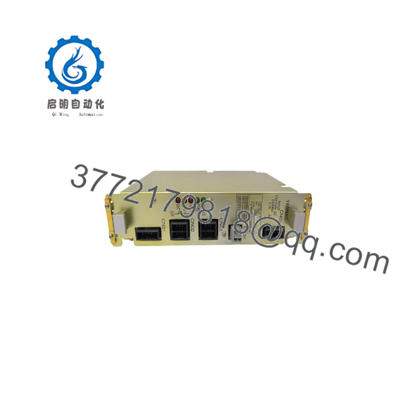
CPS-150F
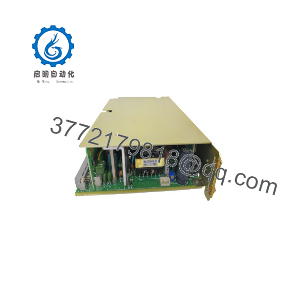
CPS-150F
Frequently Asked Questions (FAQ)
Can I hot-swap the Yaskawa ?
No. Isolate and lock out controller power before removing it. This is a controller power supply connected to mains-level cabinet wiring and internal DC distribution. Pulling it live can damage connectors, create an arc hazard, corrupt controller startup behavior, or damage connected boards. Kill power first and confirm zero energy with a properly rated meter.
Is obsolete, and can it still be purchased new?
It is a legacy spare associated with Yaskawa Motoman XRC and NX100 controller generations, so availability usually depends on surplus inventory, repair stock, or tested used units rather than current OEM production. Ask for actual photos of the item label, serial number, date code where available, and a written condition statement before placing an order. One supplier lists the item as out of stock, which is typical of legacy-spare availability.
Is a generic 150 W, 24 V DC supply a direct replacement?
No. Do not treat output wattage alone as proof of compatibility. Although some reseller listings describe the as a 150 W power supply, the verified application data identifies it as a dedicated Yaskawa controller module with 200–230 V AC input and XRC/ usage. Mechanical fit, output rails, connector pinout, sequencing, protection behavior, and controller diagnostics may differ from a generic supply.
Will I lose robot programs when I replace this power supply?
Normally, replacing the should not erase robot jobs or controller parameters because it is a power supply rather than the controller CPU or memory board. However, do not rely on that assumption during a shutdown. Back up jobs, parameters, system files, and calibration-related data before work begins. Also check encoder battery condition; a low battery can create separate position-data problems during an extended outage.
Why does the controller still show a power fault after I installed a replacement?
Start with the basic electrical path: verify the controller receives 200–230 V AC, inspect fuses and contactors, confirm transformer connections, and check protective earth. Then inspect downstream loads for a short or low-resistance fault. I have seen technicians replace the supply twice when the actual fault was a heat-damaged output connector or a downstream control board pulling a rail down during boot.
What condition should I expect: new surplus or refurbished?
A transparent supplier should identify the unit as New Original/New Surplus, Factory Sealed, or Refurbished (tested). New surplus may have older packaging or date codes but should show no installation marks, corrosion, rework, or yellowed plastic. A refurbished unit should include a test scope and warranty terms. Request clear label photos and functional-test evidence rather than accepting a generic stock image.
What testing should a supplier perform before shipment?
At minimum, ask for identity verification, visual inspection, connector inspection, powered functional testing in a compatible Yaskawa XRC or test setup, and a documented power-on result. For a used or refurbished unit, a 24-hour energized load test with temperature observation is reasonable. Test photos and videos are available upon request from a properly equipped supplier.



