WhatsApp: +86 16626708626
 Email:
 Phone: +86 16626708626
Description
Key Technical Specifications
| Parameter | Value |
|---|---|
| Manufacturer | Yaskawa Electric Corporation |
| Robot Brand | Motoman |
| Model | JANCD-XTU01B |
| Product Type | Power-On Board / PC Board Module |
| Primary Application | Motoman XRC robot controller |
| Board Function | Power-on and system startup control |
| Logic Supply | 24 VDC is reported in secondary XRC documentation |
| Installation | Controller rack / PCB assembly |
| Related Controller | Motoman XRC series |
| Reference Part Number | 142150-1, reported by secondary sources |
| Lifecycle | Discontinued / legacy |
| Related Boards | JANCD-XCP01, JANCD-XIF03-1, JANCD-XIO01B, JANCD-XIO02 |
A Yaskawa equipment list identifies JANCD-XTU01B specifically as the “Power On Board” in an XRC controller assembly. The same list places it alongside the XRC system control, communication, and I/O boards.
Secondary industrial-automation references describe the board as responsible for the controller power-up sequence and system initialization. They also associate 142150-1 with JANCD-XTU01B, but this cross-reference should be checked against the physical board label before procurement.
Product Introduction
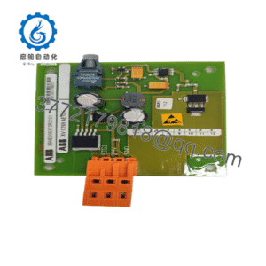
The Yaskawa JANCD-XTU01B is a legacy Power-On Board used in Motoman XRC robot controllers. Its position in the XRC controller architecture makes it part of the controller’s startup and power-control circuitry rather than a conventional robot motion-control or general-purpose I/O board.
This distinction matters during replacement. A failure of the XTU01B can affect controller startup even when the CPU, communication, and I/O boards themselves remain functional. Because the part is discontinued, replacement inventory should be matched by complete board number, revision, and physical identification rather than by board family alone.
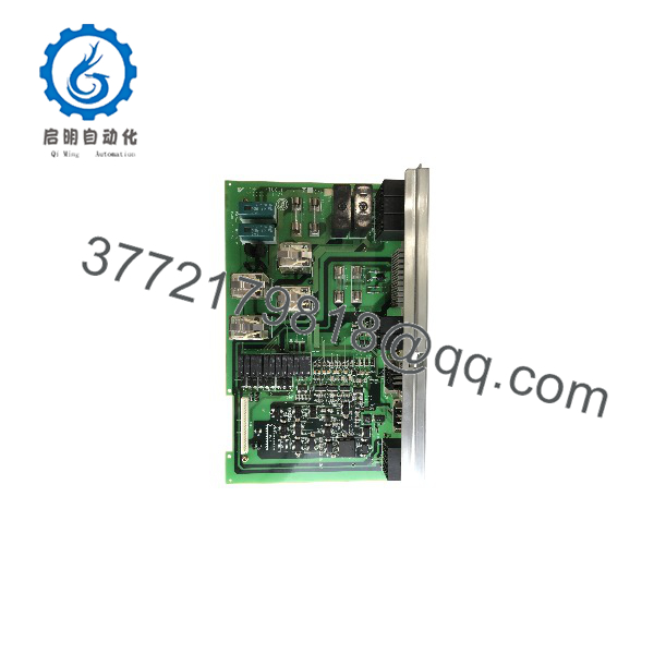
JANCD-XTU01B
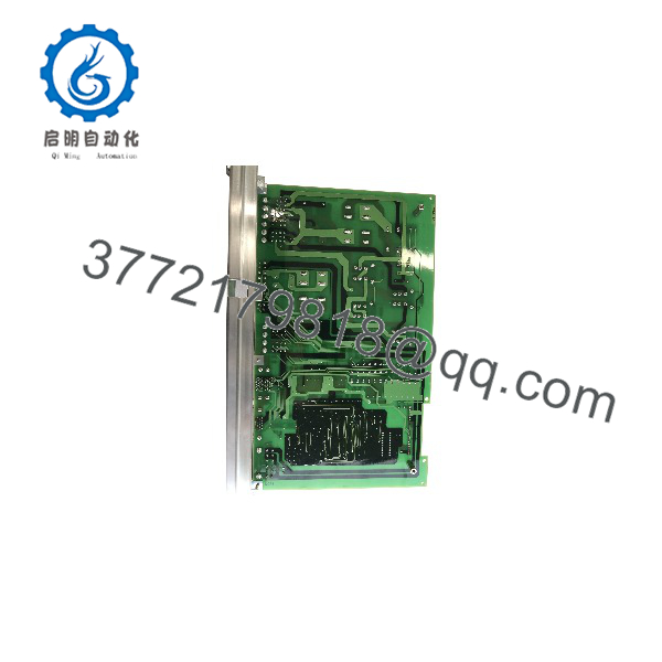
JANCD-XTU01B
Installation & Configuration Guide
Stage 1: Pre-Installation Preparation — approximately 10–15 minutes
- Confirm the exact board marking:
JANCD-XTU01B. - Confirm that the robot controller is a compatible Motoman XRC system.
- Notify operations and place the robot cell in a safe state.
- Apply the site’s LOTO procedure.
- Turn off controller power and wait for the specified discharge period.
- Photograph:
- Board position
- Connector locations
- Cable routing
- DIP switches or jumpers, if fitted
- Adjacent PCB positions
- Record the existing board revision and any secondary part number.
- Use an ESD wrist strap before touching the PCB.
⚠️ Do not assume that a board marked JANCD-XTU01 or another XTU-series number is interchangeable with JANCD-XTU01B.
Stage 2: Removing the Old Board — approximately 5–10 minutes
- Verify that controller power is completely isolated.
- Confirm that no hazardous voltage remains at the relevant power circuits.
- Label every connector before removal.
- Disconnect the connectors without pulling on the wires.
- Release the PCB retaining hardware.
- Pull the board straight out while supporting the PCB.
- Inspect the backplane connector for bent contacts, contamination, or oxidation.
- Keep the removed board for comparison.
Stage 3: Installing the Replacement — approximately 5–10 minutes
- Compare the replacement PCB with the original board.
- Verify and the board revision.
- Confirm connector positions and board layout.
- Check that no components or connector pins were damaged during shipping.
- Insert the PCB squarely into its rack connector.
- Secure the retaining hardware.
- Reconnect every connector according to the photographs and XRC wiring documentation.
- Verify that all connectors are fully seated.
- Check the controller cabinet for loose hardware or foreign objects before energizing.
⚠️ ESD control is important. This is a PCB-level controller component; handle it by the board edges and avoid touching exposed IC pins or connector contacts.
Stage 4: Power-On & Testing — approximately 10–20 minutes
- Perform a final connector and wiring inspection.
- Restore controller power according to the XRC maintenance procedure.
- Observe the controller startup sequence.
- Check whether the controller reaches its normal initialization state.
- Check for alarms or abnormal status indications.
- Confirm that the CPU, I/O, communication, and servo sections initialize normally.
- Verify robot-axis readiness before enabling motion.
- Test the emergency-stop chain and other safety interlocks.
- Perform a controlled low-speed robot test.
- Return the robot to automatic operation only after all required safety and functional checks pass.
⚠️ If the controller still fails to start after replacing the , do not assume the replacement board is defective. Check the controller power supply, emergency-stop chain, backplane connections, and other XRC power-control circuitry first.
Frequently Asked Questions (FAQ)
What is the Ya?
It is a Power-On Board used in Yaskawa Motoman XRC robot controllers. Yaskawa equipment documentation as the Power On Board within an XRC controller configuration.
a PLC I/O module?
No. It should not be treated as a conventional PLC digital I/O module. Its documented role in the XRC architecture is associated with controller power-on and startup control.
discontinued?
Yes, multiple industrial-equipment databases list as discontinued by the manufacturer. That makes condition and revision verification particularly important when sourcing a replacement.
Is 142150-1 the same part?
Several secondary sources cross-reference 142150-1. However, I would verify the number printed on the physical PCB before treating the two numbers as interchangeable purchasing references.
Can I re while the XRC controller is powered?
No. Treat the PCB as a de-energized replacement component unless the exact Yaskawa maintenance documentation explicitly permits otherwise. Isolate power and follow the controller’s discharge and LOTO requirements.
What should I check if the replacement does not solve a startup failure?
Start with the controller power supply, E-stop circuit, connectors, backplane, and related XRC control boards. The is only one element of the startup circuit. Replacing it without checking the upstream and downstream power-control paths can result in unnecessary board replacement.
What condition should I specify when purchasing this board?
For a discontinued XRC board, specify the condition explicitly: Factory Sealed/New Original, New Surplus, or Refurbished/Tested. For refurbished inventory, request functional-test evidence and clear photographs of the actual PCB, including the model and revision markings.