WhatsApp: +86 16626708626
 Email:
 Phone: +86 16626708626
Description
Key Technical Specifications
| Parameter | Value |
|---|---|
| Manufacturer | Yaskawa Electric |
| Series | MEMOCON GL120 |
| Model | JRMSI-120XBP01200 |
| Mounting base designation | MB12 |
| Number of slots | 12 |
| Product category | PLC mounting base / rack |
| Compatible system | MEMOCON GL120 |
| Module connection | Internal module connector/backplane interface |
| Mounting provisions | Panel mounting and DIN-track slide lock |
| Mounting screw | M5 |
| Approx. mass | 1,110 g |
| Related base models | MB06, MB08, MB10, MB16 |
The MEMOCON GL120 hardware manual specifically lists MB12 = JRMSI-120XBP01200, with 12 slots. It also states that mounting bases are used to install various modules, including CPU modules.
The published dimensions documentation gives an approximate mass of 1,110 g and identifies M5 mounting holes and the DIN-track slide-lock arrangement.
Product Introduction
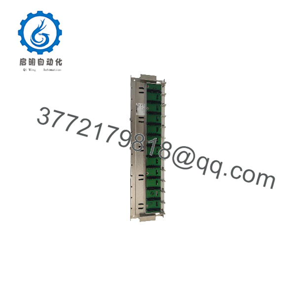
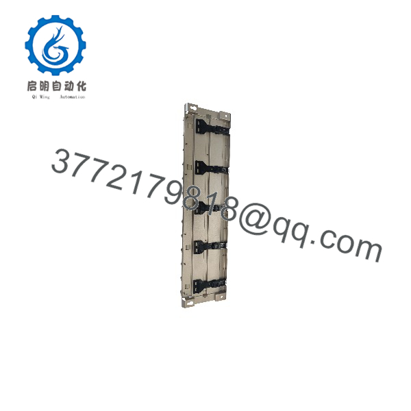
The Yaskawa JRMSI-120XBP01200 is the MB12 mounting base for a MEMOCON GL120 PLC station. It provides the mechanical mounting and module interconnection structure for up to 12 GL120 module positions, including CPU and I/O modules.
This component is a rack/base assembly, not a CPU, power supply, or I/O module. For maintenance work, matching the exact slot count and GL120 hardware family is essential before replacement.
JRMSI-120XBP01200
JRMSI-120XBP01200
Installation & Configuration Guide
Stage 1 — Prepare the PLC cabinet
- Confirm that the existing rack is identified as JRMSI-120XBP01200 / MB12.
- Record the installed module positions from left to right.
- Photograph the rack, module arrangement, connectors, and wiring.
- Confirm the replacement rack has the same slot configuration.
- Apply LOTO procedures before removing the existing assembly.
Estimated preparation time: 20–30 minutes.
⚠️ Do not treat this rack as a generic 12-slot PLC backplane. Its module interface is associated with the MEMOCON architecture.
Stage 2 — Remove the existing mounting base
- Switch off the applicable control power.
- Verify the absence of hazardous voltage with an appropriately rated meter.
- Label connected wiring and module positions.
- Remove the installed modules according to the hardware manual.
- Release the mounting hardware and remove the base without stressing the module connectors.
The documentation identifies a module hook, module connector, and DIN-track slide lock as part of the MB12 mounting-base construction.
Stage 3 — Install the JRMSI-120XBP01200
- Inspect the replacement rack for bent contacts, cracked insulation, corrosion, or mechanical damage.
- Position the base using the existing cabinet mounting pattern.
- Secure the mounting base using the specified mounting hardware.
- Verify the DIN-track locking mechanism if DIN mounting is used.
- Reinstall the modules in their original positions.
- Check that every module is fully engaged with the rack connector.
⚠️ Never force a module into the rack. Connector alignment must be correct before applying insertion pressure.
Stage 4 — Power-up and verification
- Recheck all module positions against the original photographs.
- Verify power-supply and CPU module placement.
- Restore control power according to the machine procedure.
- Check CPU and module status indicators.
- Verify I/O communication and station operation.
- Confirm that the PLC executes the expected program without rack or module errors.
Estimated installation and testing time: 1–2 hours, depending on cabinet accessibility and module count.
FAQ
What is Yaskawa JRMSI-120XBP01200?
It is the 12-slot MB12 mounting base for the Yaskawa MEMOCON PLC system. It provides the rack structure and module connection interface for the installed modules.
Is a PLC CPU?
No. It is a mounting base/rack. The CPU, power supply, I/O, and other functional modules are installed on the mounting base.
How many modules can the rack accommodate?
The configuration provides 12 module slots. Yaskawa’s documentation also lists MB06, MB08, MB10, and MB16 versions with different slot capacities.
Can I replace it with a 10-slot or 16-slot rack?
Not as a simple drop-in substitution. A different slot count changes the physical rack configuration and may affect cabinet dimensions, module allocation, and wiring. Use the exact when the existing installation requires the 12-slot arrangement.
Does replacing the mounting base erase the PLC program?
The mounting base itself is not the PLC CPU or program-storage device. However, the complete system should still be backed up before maintenance because configuration, wiring, and module-position errors can cause startup problems.
Is obsolete?
It belongs to the legacy platform. Current market listings classify the part as a legacy spare, with new-surplus and refurbished examples available.
Can it be replaced by a Mitsubishi PLC base?
Mitsubishi documentation does show MEMOCON GL-series mounting bases, including , in PLC modernization references to MELSEC iQ-R base units. However, this is a migration reference, not evidence that a Mitsubishi base is a direct mechanical or electrical replacement. A modernization project requires a complete hardware and software compatibility review.