
 WhatsApp: +86 16626708626
 Email:
  Phone: +86 16626708626
Description
Key Technical Specifications
| Parameter | Value |
|---|---|
| Manufacturer | Yaskawa |
| Full Model Number | SGMJV-04ADE6S |
| Product Family | Sigma-5 |
| Motor Series | SGMJV |
| Product Type | Brushless AC rotary servo motor |
| Rated Output | 400 W |
| Rated Voltage | 200 V AC |
| Rated Current | 2.7 A |
| Rated Torque | 1.27 N·m |
| Rated Speed | 3,000 rpm |
| Maximum Speed | 6,000 rpm |
| Motor Inertia Class | Medium inertia |
| Peak Torque Capability | Up to 350% of rated torque for the SGMJV family |
| Feedback | High-resolution serial encoder; confirm the exact encoder configuration from the motor nameplate and matched SERVOPACK documentation |
| Shaft / Brake / Connector Details | Confirm from the complete nameplate code and mechanical drawing before purchase or installation |
| Compatible Drive Platform | Matched Yaskawa Sigma-5 SERVOPACK; verify drive model, feedback type, cable part numbers, and motor-selection parameters |
| Lifecycle Status | Sigma-5 family; verify regional product support and exact model availability with Yaskawa or an authorized channel before committing to long-term stocking |
| Stocking Recommendation | Min: 1 unit for each critical unique axis configuration; Max: 2 units only for common multi-machine applications, long replacement lead times, or outage costs exceeding carrying-cost targets |
Yaskawa lists the SGMJV family as a 50 W to 750 W medium-inertia Sigma-5 servo-motor range with 6,000 rpm maximum speed and 13- or 20-bit high-resolution serial encoder options. Product listings for this exact model state 400 W, 200 V AC, 2.7 A, 1.27 N·m rated torque, 3,000 rpm rated speed, and 6,000 rpm maximum speed.
Product Introduction & Supply Chain Strategy
The Yaskawa SGMJV-04ADE6S is a 400 W Sigma-5 AC rotary servo motor for precision positioning, speed regulation, and controlled motion axes. Its medium-inertia design suits compact automation systems that require stable motion response, such as packaging equipment, assembly machinery, indexing tables, material handling equipment, and general-purpose machine axes.
This product is a Brand New Surplus unit. It is not used, not pulled from a decommissioned plant, and not refurbished. All modules undergo rigorous quality verification to ensure OEM-level reliability. For a critical 400 W axis, one verified buffer stock motor is usually the lowest-TCO choice. Hold a second unit only when lead time variability, installed-base commonality, or lost-production cost justifies its carrying cost. Use vendor consolidation and documented cross-site sharing before expanding stock levels.
Installation & Configuration Guide
Stage 1: Pre-Installation
- Stop the machine through the approved production shutdown process. Record active servo alarms, axis position, homing status, following error, motor current, and controller diagnostics.
- Apply lock-out/tag-out to main AC power, servo power, 24 V control circuits, pneumatic or hydraulic energy, gravity-loaded mechanisms, and any external motion source.
- Verify absence of voltage at the servo drive and wait for the DC bus to discharge according to the machine and Yaskawa documentation.
- Wear a grounded ESD wrist strap before touching encoder feedback connectors, drive control wiring, or exposed electronic interfaces.
- Photograph the original motor nameplate, shaft coupling, mounting flange, cable routing, connector orientation, grounding points, brake wiring, and any cable labels.
- Confirm the complete replacement model number, including all suffixes. Verify rated output, rated voltage, encoder type, brake configuration, shaft style, flange dimensions, cable-exit direction, connector layout, and environmental rating.
- Back up the Sigma-5 SERVOPACK parameters and controller program before removing the motor. Preserve motor selection, encoder settings, electronic gearing, speed limits, torque limits, homing parameters, tuning values, brake timing, and travel limits.
- Inspect the driven mechanism for binding, damaged bearings, misaligned couplings, contamination, excessive inertia, loose hardware, or a failed brake. Do not install a replacement motor until the failure cause is understood.
Stage 2: Removal
- Confirm that the servo-drive DC bus has discharged completely before disconnecting power or feedback cables.
- Mechanically secure vertical or suspended loads. Do not rely on a motor holding brake as a maintenance support device.
- Mark the coupling, pulley, gearbox, or timing-belt position if the machine’s mechanical reference depends on the existing relationship.
- Disconnect protective earth, motor power, encoder feedback, brake wiring, and auxiliary connections by connector housing or terminal hardware. Never pull on the cable conductors.
- Protect encoder connectors from contamination, impact, moisture, and electrostatic discharge.
- Support the motor before removing mounting hardware. Avoid striking the shaft, prying against the flange, or placing side load on the encoder end.
- Inspect the shaft, key, coupling, mounting pilot, feedback cable, motor cable, and connector contacts. Replace damaged supporting hardware before fitting the New Surplus motor.
Stage 3: Installation
- Compare the replacement motor nameplate against the removed motor one final time. Do not proceed if any full-code suffix, shaft feature, brake option, connector type, or feedback configuration differs.
- Install the motor squarely on the machine mounting surface and tighten mounting bolts to the machine builder’s specified torque.
- Align the coupling or transmission component. Excessive radial or angular misalignment increases bearing loading, vibration, heat, and encoder-related motion faults.
- Secure the shaft interface using the specified key, clamp, coupling, or pulley hardware. Confirm that the coupling does not bottom out or apply axial preload to the motor shaft.
- Connect protective earth first, then motor power, brake wiring, encoder feedback, and auxiliary circuits.
- Route feedback cables separately from motor power conductors and high-noise circuits. Restore the original shielding and grounding arrangement.
- Confirm that all connector locks are fully engaged and that cable routing provides strain relief without sharp bends.
- Load only the approved parameter backup that matches the exact motor and drive combination.
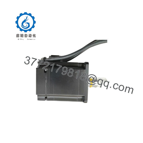
SGMJV-04ADE6S
Stage 4: Power-On & Testing
- Before applying full power, test the 24 V control rail and confirm no short exists between control circuits and ground.
- Apply control power, where permitted by the machine sequence, and inspect the SERVOPACK for encoder, motor, communication, or configuration alarms.
- Verify emergency-stop circuits, overtravel limits, safety interlocks, brake-release logic, and servo-enable sequencing before enabling motion.
- Enable the axis at low speed with the guarded work area clear. Confirm correct direction, actual-position feedback, command-position tracking, motor current, brake operation, and absence of abnormal vibration or noise.
- Run a low-speed jog, then perform the approved homing routine. Confirm home position, limit response, and following-error behavior.
- Test at progressively higher speed and load while monitoring current, servo alarms, temperature, vibration, and position error.
- Return the machine to production only after completing its documented functional acceptance test. Record the motor serial number, parameter-file revision, test result, installation date, and remaining buffer stock.
Firmware/Software Versions & Upgrade Notes
- Recommended firmware version: Retain the existing Sigma-5 SERVOPACK firmware and validated parameter revision during a direct motor replacement. The motor does not normally have a user-managed firmware upgrade process; compatibility depends on the matched SERVOPACK, the high-resolution serial encoder, motor-selection parameters, and the controller interface.
- Drive configuration: Select the exact SGMJV-04ADE6S configuration specified by the Yaskawa drive setup procedure. Do not configure the drive merely for a generic 400 W motor.
- Encoder compatibility: Yaskawa specifies high-resolution serial encoder options within the SGMJV family. Verify the exact feedback arrangement on the motor label and ensure the existing feedback cable and SERVOPACK support it before applying power.
- Backward compatibility: Earlier Sigma generations may not accept Sigma-5 encoder feedback, motor cables, or parameter files. A legacy drive replacement can require a matched motor-drive-controller migration rather than a motor-only change.
- Forward compatibility: A newer Yaskawa motion platform may require different feedback cables, drive parameters, controller communication settings, safety architecture, and retuning. Mechanical interchangeability alone does not establish electrical or motion compatibility.
- Upgrade warning: Do not update SERVOPACK firmware during an emergency motor swap unless the existing firmware is unavailable and the revised firmware has been tested with the machine program. Firmware changes can alter alarm handling, communications, parameter interpretation, and tuning behavior.
- Downgrade warning: Do not downgrade a drive without a verified firmware image and recovery method. A failed downgrade can disable the axis and extend the stock-out event.
- Spare documentation: Store a motor nameplate photograph, drive parameter backup, axis tuning record, cable part numbers, mechanical drawing, and commissioning checklist with the on-site buffer stock.
Frequently Asked Questions (FAQ)
Are these really new units?
Yes. This inventory standard applies to New Original / New Surplus inventory only. The motor should be original OEM-manufactured stock with no installation wear on the shaft, flange pilot, mounting surfaces, connectors, or cable exits. Incoming QC should verify part number, serial number, packaging condition, shaft condition, connector integrity, insulation condition, and encoder-feedback function.
Why does New Surplus cost less than OEM new but more than lower-priced alternatives?
OEM-new pricing reflects current factory supply channels and standard support structures. New Surplus pricing reflects the cost of sourcing, validating, storing, and warranting genuine inventory. Lower-priced alternatives can carry hidden exposure from prior loading, bearing wear, shaft damage, encoder faults, moisture storage, or undocumented modifications. For a critical motion axis, the relevant financial comparison is Total Cost of Ownership (TCO): purchase cost plus replacement labor, downtime, lost output, and repeat-failure risk.
Is the SGMJV-04ADE6S obsolete or EOL?
The SGMJV family remains published by Yaskawa as a Sigma-5 product family, but exact regional availability and lifecycle status for the full SGMJV-04ADE6S configuration must be verified before planning a long-term supply strategy.
For inventory purposes, classify it as a controlled critical spare until the manufacturer or authorized supplier confirms current production, official discontinuation, or a replacement path. Maintain one unit on-site if the axis can stop production and no qualified cross-site spare is available within the required recovery window.
Can I hot-swap this servo motor?
No. Do not disconnect or reconnect the motor while the servo system is energized. Isolate incoming power, verify DC bus discharge, secure any gravity-loaded axis mechanically, and follow the machine builder’s approved replacement procedure. Hot-swapping can damage the motor, encoder circuit, SERVOPACK, or machine controller and can create a serious personnel hazard.
Will a motor swap erase machine programming?
The PLC, CNC, or motion controller normally retains its logic. However, the SERVOPACK can contain motor selection, tuning, electronic gear, homing, speed limit, torque limit, brake timing, and encoder-related parameters. Back up the drive and controller before removal, then verify the restored configuration during commissioning.
Can I substitute another 400 W Yaskawa motor?
Not without an engineering-approved cross-reference. Matching the 400 W rating alone is not enough. You must confirm rated speed, torque, inertia, encoder type, brake option, shaft type, flange size, connector arrangement, cable compatibility, drive motor-selection code, load inertia, and safety behavior. Treat a different motor family as a motion-system modification, not a routine spare swap.
What warranty and quality records should be required?
Specify a written 12- to 24-month warranty subject to correct storage, installation, and operation. Require nameplate and serial-number photographs, original-package evidence, visual inspection records, insulation and protective-earth checks where applicable, encoder feedback verification, and final QC sign-off. Retain these records with the asset history so maintenance can install the motor quickly and confidently during an unplanned failure.



