
 WhatsApp: +86 16626708626
 Email:
  Phone: +86 16626708626
Description
Key Technical Specifications
| Parameter | AAI143-H50K4A00 Specification |
|---|---|
| Manufacturer | Yokogawa Electric Corporation |
| Model | AAI143-H50K4A00 |
| Product Type | Isolated analog input module |
| Number of Channels | 16 |
| Input Signal | 4–20 mA DC |
| Allowable Input Current | 24 mA |
| Input Resistance, Power ON | 270 Ω at 20 mA to 350 Ω at 4 mA |
| Input Resistance, Power OFF | 500 kΩ or higher |
| Accuracy | ±16 µA |
| Data Update Period | 10 ms |
| Isolation Withstand Voltage | 1,500 V AC for 1 minute, input-to-system |
| Transmitter Supply | ≥19.0 V at 20 mA; ≤25.5 V at 0 mA |
| Transmitter Supply Current Limit | 25 mA |
| Transmitter Configuration | 2-wire / 4-wire, channel-selectable |
| HART Communication | Supported |
| Power Consumption | 230 mA at 5 VDC; 540 mA at 24 VDC maximum |
| Interface | KS cable interface adapter |
| Adapter | ATK4A-00 |
| Weight | Approximately 0.3 kg |
The AAI143 specification identifies this family as a 16-channel isolated 4–20 mA analog input module. The H50 suffix indicates HART digital communication, while the /K4A00 option provides the KS Cable Interface Adapter for connection to the applicable terminal-board arrangement.
The published specifications also identify a 10 ms data-update period, ±16 µA accuracy, 1,500 V AC input-to-system withstand voltage, and transmitter power suitable for 2-wire transmitters.
Product Introduction
The Yokogawa AAI143-H50K4A00 is a 16-channel isolated analog input module for Yokogawa FIO-based control systems. It accepts standard 4–20 mA process signals and adds HART communication capability, allowing compatible smart field instruments to provide digital device information over the analog loop. The module supports both 2-wire and 4-wire transmitter arrangements, with the transmitter configuration selected per channel.
The /K4A00 portion of the ordering code is important for cabinet integration. It specifies the KS Cable Interface Adapter, identified as ATK4A-00, for connection to the appropriate Yokogawa terminal-board arrangement. This means procurement should verify not only the AAI143-H50 base module but also the existing terminal board and KS cable architecture before substituting another AAI143 variant.
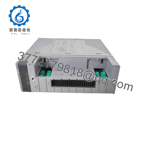
AAI143-H50K4A00
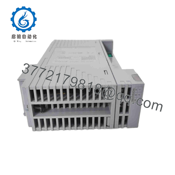
AAI143-H50K4A00
Installation & Configuration Guide
Stage 1 — Pre-Installation Preparation
Before replacing an -H50K4A00:
- Confirm the Yokogawa DCS model and FIO node configuration.
- Verify the complete ordering code: .
- Confirm that the existing application requires 16 isolated 4–20 mA inputs.
- Check whether HART communication is being used by the control or asset-management system.
- Verify the installed terminal board and KS cable arrangement.
- Back up the current I/O configuration and record channel assignments.
- Photograph the module, cable connection, and terminal-board arrangement.
- Follow the plant LOTO procedure where the replacement requires de-energizing the applicable equipment.
- Observe ESD precautions when handling the module.
A common procurement mistake is ordering when the existing cabinet requires the /K4A00 KS interface arrangement. Confirm the complete suffix before installation.
Stage 2 — Removing the Existing Module
- Place the DCS node in the approved maintenance state.
- Confirm the relevant I/O channels and process loops are safe.
- Follow the Yokogawa-approved module replacement procedure.
- Disconnect or release the KS interface connection as applicable.
- Release the module retaining mechanism.
- Remove the module without stressing the backplane or interface connector.
- Inspect the connector and surrounding hardware.
- Check the existing module for signs of:
- Overheating
- Corrosion
- Connector damage
- Contamination
- Mechanical damage
- Retain the removed module for failure analysis if required.
If the module is being replaced because several channels failed simultaneously, inspect the interface cable, terminal board, field power, and common system conditions before assuming the itself is defective.
Stage 3 — Installing the -H50K4A00
- Verify the replacement label and full model number.
- Confirm the module is the H50 HART-enabled version.
- Confirm the /K4A00 interface option.
- Inspect the connector for bent, contaminated, or damaged contacts.
- Install the module in the correct FIO position.
- Secure the module according to the Yokogawa hardware procedure.
- Reconnect the KS interface.
- Confirm cable routing and connector seating.
- Verify each channel’s 2-wire or 4-wire transmitter configuration.
- Check the DCS database against the recorded channel assignment.
The supports channel-by-channel selection of 2-wire or 4-wire transmitter operation. This setting should be reproduced from the approved engineering configuration rather than assumed from the physical wiring alone.
Stage 4 — Power-On & Testing
After installation:
- Confirm the module is correctly seated.
- Verify the FIO node status.
- Check module diagnostics and status indicators.
- Confirm all expected channels are recognized.
- Inject or simulate known 4–20 mA signals where the commissioning procedure permits.
- Verify the DCS engineering values against the injected current.
- Check channel scaling and alarm limits.
- Confirm transmitter loop power where 2-wire transmitters are used.
- Verify HART communication with representative smart transmitters if HART is part of the application.
- Confirm redundant-node behavior if the module is installed in a dual-redundant architecture.
For HART applications, Yokogawa-related documentation notes that the relevant remote-node firmware must meet the required revision for HART functionality. Verify the actual node firmware before commissioning rather than assuming every legacy node revision supports the HART feature.
Technical Pitfalls to Check
HART vs. standard analog operation
The H50 suffix is not merely a mechanical revision; it identifies the HART-capable version. Replacing it with an S50 module can preserve the 4–20 mA measurement function while removing the required digital communication capability.
KS interface mismatch
The K4A00 option matters when the cabinet uses the corresponding KS cable architecture. Verify the terminal board, adapter, and cable combination before changing the module ordering code.
Intrinsically safe applications
The H50 variant is identified as the version without explosion protection. In an intrinsically safe installation, the correct isolation-barrier arrangement must be used; the published information specifically states that a Zener barrier should not be connected directly to this module.
Frequently Asked Questions (FAQ)
1. What is Yokogawa -H50K4A00?
It is a 16-channel isolated analog input module that accepts 4–20 mA signals and supports HART digital communication. The /K4A00 option provides the KS Cable Interface Adapter.
2. How many analog inputs provide?
It provides 16 isolated 4–20 mA input channels.
3. support HART?
Yes. The -H suffix identifies the HART-capable version of the module. HART digital communication can be used with compatible smart field instruments.
4. What is the difference between -H5?
The base module is . The option adds the KS Cable Interface Adapter, identified as ATK4A-00, for the applicable terminal-board connection.
5 handle both 2-wire and 4-wire transmitters?
Yes. The published specification provides a per-channel setting for 2-wire or 4-wire transmitter operation.
an intrinsically safe module?
The H50 variant is the non-explosion-protection version. For hazardous-area applications, the complete signal interface and isolation-barrier design must be checked against the applicable Yokogawa system documentation.
7. Can I re with another module?
Not without checking the complete ordering code. Differences in HART capability, explosion-protection option, temperature/G3 option, terminal interface, and cabinet wiring can affect compatibility. The replacement should match the existing system design and terminal-board configuration.
8. What should procurement verify before purchasing this module?
Verify all of the following:
- Exact model:
- 16-channel isolated 4–20 mA configuration
- HART requirement
- / KS interface
- Existing terminal board
- KS cable type
- DCS/FIO node compatibility
- Firmware requirements for HART operation
- Module condition and revision
- Functional-test or inspection records
- Warranty and traceability
For a legacy DCS installation, matching the complete ordering code and cabinet interface is more important than matching only the base number.



