
 WhatsApp: +86 16626708626
 Email:
  Phone: +86 16626708626
Description
Key Technical Specifications
| Parameter | Specification |
|---|---|
| Model | CP451-10 |
| Manufacturer | Yokogawa Electric Corporation |
| Module Type | FCS Processor Module |
| Applicable DCS | CENTUM VP |
| Compatible FCS | AFV10S, AFV10D |
| Processor Function | Real-time control and FCS processing |
| System Network | Vnet/IP |
| Processor Redundancy | Dual-redundant configuration supported |
| FCS Power Supply | 100–120 V AC, 220–240 V AC, or 24 V DC, depending on FCU configuration |
| FCS Power Consumption | 200 VA at 100–120 V AC; 230 VA at 220–240 V AC; 5.5 A at 24 V DC |
| FCS Weight | Approximately 7 kg AFV10S / 8 kg AFV10D |
| Mounting | CENTUM Field Control Unit |
| I/O Capacity | Up to 8 I/O modules in the documented AFV10S/AFV10D configuration |
| Processor Redundancy | Two CP451 modules for dual-redundant configuration |
Yokogawa’s official CENTUM documentation identifies CP451 as the FCS processor module and specifies AFV10S and AFV10D as applicable field control units. The same documentation describes two CP451 modules in a dual-redundant configuration.
Important: Public supplier pages frequently mix CP451-10 specifications with other CP451 revisions or even unrelated I/O-module data. Values such as memory size, processor frequency, scan time, and individual module power consumption should therefore not be treated as confirmed -10 specifications without the complete Yokogawa style code.
Product Introduction
The Yokogawa CP451-10 is an FCS processor module used in CENTUM VP distributed control systems. It provides the processor function within the Field Control Unit, executing control applications and coordinating the FCS with the Yokogawa control network. Yokogawa documentation specifically identifies as the processor module for AFV10S and AFV10D FCS configurations.
For maintenance teams supporting legacy CENTUM installations, the exact processor style is critical. hardware should be matched to the applicable FCS model, redundant arrangement, and system revision rather than selected solely by the family name.
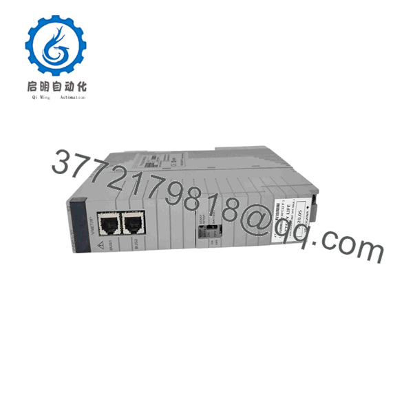
CP451-10
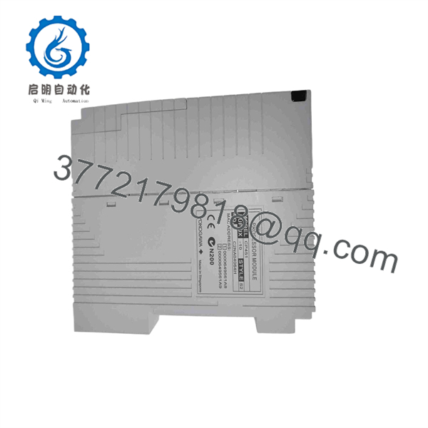
CP451-10
Installation & Configuration Guide
Stage 1: Pre-Installation Preparation — 5–10 Minutes
- ⚠️ Notify operations and place the affected process in the approved maintenance state.
- Apply plant LOTO procedures where power isolation is required.
- Confirm whether the FCS is operating in a redundant configuration.
- Prepare:
- ESD wrist strap
- PH1 screwdriver
- Digital multimeter
- Wire labels
- Smartphone or camera
- Record the complete nameplate information:
- -10 model
- Full style/suffix code
- Hardware revision
- Serial number
- Firmware revision, if available
- Photograph the installed processor position, connectors, status LEDs, and rack arrangement.
- Back up the applicable CENTUM engineering/control configuration before removal.
⚠️ Do not use the base number alone as the replacement criterion. Yokogawa’s official documentation identifies different processor families and FCS combinations, including for AFV10S/AFV10D and CP461/CP471 for later FCU families.
Stage 2: Removing the Old Module — Approximately 5 Minutes
- Confirm the FCS maintenance condition and processor redundancy status.
- Verify the required electrical isolation.
- Release the processor module’s retaining mechanism.
- Disconnect the relevant network/backplane connections carefully.
- Pull the module straight out of its designated slot.
- Inspect the connector and backplane for contamination, bent contacts, or mechanical damage.
- Keep the removed processor available until the replacement has completed commissioning.
Stage 3: Installing the New Module — Approximately 5 Minutes
- Wear a grounded ESD strap before handling the replacement.
- Compare the complete part number and hardware revision with the removed .
- Confirm that the FCS is an applicable or configuration.
- Verify the processor position within the FCS.
- If operating with redundant processors, confirm the correct primary/secondary position.
- Insert the module carefully into the designated slot.
- Secure the module using the original retaining mechanism.
- Reconnect the applicable communication and backplane connections.
- Inspect the installation before applying power.
Stage 4: Power-On & Testing — Approximately 10–15 Minutes
- Before energizing, check the applicable supply circuit with a multimeter.
- Power the FCS according to the Yokogawa maintenance procedure.
- Observe the status indicators during startup.
- Confirm that the processor completes its initialization sequence.
- Verify FCS communication with the CENTUM engineering and operator stations.
- Check processor redundancy status where a dual-processor arrangement is installed.
- Confirm that the expected control application is available.
- Verify representative I/O values.
- Check control loops, alarms, sequence functions, and interlocks.
- Return the process to normal operation only after the FCS diagnostics and control functions have been verified.
Field troubleshooting notes:
- Processor will not initialize: Check exact style code, FCS compatibility, firmware, and backplane condition.
- Redundant pair will not synchronize: Compare processor revisions and the configured processor positions.
- Network communication fault: Inspect the Vnet/IP connection and associated FCS network hardware.
- Control application unavailable: Verify the engineering database and application configuration before attempting a download.
- Unexpected behavior after replacement: Stop configuration changes and compare the replacement hardware/firmware against the original unit first.
Yokogawa’s security advisory also explicitly lists as a CENTUM VP controller FCS processor module and associates it with and FCS models.
FAQ
Q1. What is the Yokogawa -10?
-10 is a Yokogawa FCS processor module used within applicable CENTUM control-system hardware. It performs the central processing function for the Field Control Station.
Q2. Which FCS models are associated with the processor?
Yokogawa documentation identifies the processor with CENTUM VP Field Control Units.
Q3. Does support processor redundancy?
Yes. Yokogawa’s CENTUM documentation specifies two processor modules for a dual-redundant FCS configuration.
Q4. directly replace another processor?
Not automatically. Confirm the complete ordering/style code, FCS model, hardware revision, firmware compatibility, and redundant configuration before installation.
Q5 compatible with CP461 or CP471?
They belong to different processor families. Yokogawa documentation separately identifies , CP461, and CP471 and associates them with different FCS generations/models. A cross-family replacement should therefore be based on Yokogawa compatibility documentation rather than physical fit alone.
Q6 an obsolete module?
It is best treated as a legacy CENTUM processor spare for maintenance planning. Current secondary-market listings still o units, including used and new-surplus examples, but listing availability does not establish current OEM production status.
Q7. What should I provide when sourci replacement?
Provide the complete nameplate photograph, full style/suffix code, serial number, hardware revision, FCS model, and processor redundancy arrangement. This information is much more useful than the base designa alone.
F replacement, verify the FCS model and complete Yokogawa style code before committing the spare to the installation.



