WhatsApp: +86 16626708626
 Email:
 Phone: +86 16626708626
Description
Key Technical Specifications
| Parameter | Specification |
|---|---|
| Model number | NFDV551-P10 |
| Manufacturer | Yokogawa |
| Module type | Digital output |
| Output technology | Transistor, sink type |
| Number of outputs | 32 channels |
| Rated load voltage | 24 VDC |
| Permissible load voltage | 20.4–26.4 VDC |
| Maximum load current | 100 mA per channel |
| Maximum ON-state voltage drop | 2 VDC, as reported by third-party listings |
| OFF-state leakage current | 0.1 mA maximum, as reported by third-party listings |
| Output-to-system isolation | 2 kVAC, as reported by third-party listings |
| Isolation between common groups | 500 VAC, as reported by third-party listings |
| Output response time | 3 ms maximum, as reported by some supplier listings |
| External connection | MIL 50-pin connector or compatible terminal accessory |
| Reported dimensions | 32.8 × 107.5 × 130 mm |
| Reported weight | Approximately 0.2–0.3 kg |
| System compatibility | Verify against the applicable Yokogawa controller and I/O documentation |
Specification caution: These figures are reported in third-party product listings; I could not verify them against an official Yokogawa datasheet during this search. Confirm electrical ratings, isolation, environmental limits, and accessory compatibility before using them for engineering approval or procurement.
Product Introduction
The YOKOGAWA NFDV551-P10 is listed as a 32-channel digital output module for industrial automation systems. Its reported sink-type transistor outputs switch discrete DC signals to compatible field interfaces, supporting applications such as relay control, indicator signaling, and low-current actuator interfaces. Before integrating or replacing this module, engineers should verify the output wiring topology, field-load current, controller compatibility, and terminal arrangement against the installed system’s documentation.
Installation & Configuration Guide
Confirm the replacement part
- Compare the complete model number on the existing module nameplate.
- Check the controller family and I/O configuration in the system documentation.
- Verify whether the installation requires a MIL connector cable, a pressure-clamp terminal block, or a specific connector cover.
- Do not assume that a similarly named Yokogawa module has the same output circuitry or pin assignment.
Isolate the equipment
- Place the controlled equipment in a safe state.
- Isolate the applicable system and field power sources using the site’s lockout/tagout procedure.
- Confirm the absence of hazardous voltage before removing connectors or handling field wiring.
Inspect field wiring
- Identify the common connections and output-channel assignments from the applicable wiring diagram.
- Confirm that the connected loads are compatible with sink-type outputs.
- Verify that the field supply remains within the specified voltage range and that no channel exceeds its allowable current.
- Use an interposing relay or suitable external driver when the load exceeds the module’s verified rating.
Install and configure
- Fit the module and its accessories according to the manufacturer’s installation instructions.
- Check connector orientation, terminal retention, grounding, and wiring labels.
- Confirm channel assignments and output fallback behavior in the controller configuration. Do not assume a default fallback state without checking the relevant manual.
Commission the module
- Restore power in accordance with the site’s approved startup procedure.
- Verify module recognition and channel status indications.
- Test outputs individually under controlled conditions.
- Confirm the commanded state at each field device and investigate unexpected switching, output faults, or communication alarms before returning the equipment to service.
Engineering note: Obtain the official Yokogawa manual for the installed system before performing live testing or changing safety-related logic. The steps above are general commissioning guidance, not model-specific instructions.
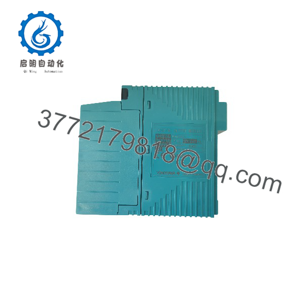
NFDV551-P10
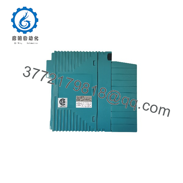
NFDV551-P10
Frequently Asked Questions
Q1: What is the NFDV551-P10 used for?
It is listed as a digital output module for switching discrete signals to compatible field devices in industrial control systems. Confirm the exact system application from the installed hardware documentation.
Q2: How many output channels does it have?
Third-party product references identify the NFDV551-P10 as a 32-channel digital output module.
Q3: Does it use relay outputs or transistor outputs?
Supplier listings describe it as a sink-type transistor output module, rather than a mechanical relay-output module. Verify this against the official hardware documentation before connecting field loads.
Q4: What field voltage does it support?
Listings report a nominal 24 VDC load supply and a permissible range of 20.4–26.4 VDC. Confirm the exact limits in the relevant Yokogawa manual before energizing the circuit.
Q5: Can it directly drive a solenoid valve?
Only if the valve’s electrical requirements fall within the module’s verified output ratings. Check steady-state current, inrush current, inductive-load suppression, and the manufacturer’s permitted load types. Use an appropriately rated interposing device when necessary.
Q6: Is the NFDV551-P10 compatible with every Yokogawa controller?
No universal compatibility should be assumed. Supplier listings associate it with STARDOM FCN/FCJ systems, but the specific controller, I/O architecture, mounting arrangement, and firmware or configuration requirements must be checked.
Q7: What should be checked before purchasing a replacement?
Verify the complete model and suffix, the existing module’s nameplate, connector and terminal accessories, channel count, output type, electrical ratings, and controller compatibility. Request a nameplate photo and documentation from the supplier if the unit’s revision or condition is uncertain.