WhatsApp: +86 16626708626
 Email:
 Phone: +86 16626708626
Description
Core Product Summary (Brand / Model / Key Attributes)
The Yokogawa UP55A-001-11-00 is a 1/4 DIN panel-mounted program controller from the UTAdvanced series, designed for automated batch profiling, thermal processing, and process ramp/soak applications. It features a high-visibility, 14-segment active color LCD display capable of changing color based on alarm or control states, along with dedicated navigation keys and a short 65 mm panel depth for space-constrained enclosures. As part of the UP55A family, it provides up to 30 program patterns and 300 program segments, integrated ladder sequence logic execution, and universal input/output support.
Model code configuration UP55A-001-11-00 designates the standard control type operating on a 100–240 V AC supply voltage. The unit includes RS-485 serial communication supporting Modbus RTU, Modbus ASCII, PC-Link, and ladder protocols at baud rates up to 38.4 kbps. Standard physical I/O capabilities include 8 digital inputs, 8 digital outputs, and a switchable retransmission output / 15 V DC loop power supply capability. The unit features an English display default (switchable to German, French, or Spanish) housed in a black (light charcoal gray) bezel enclosure.
Key Technical Specifications
| Parameter | Specification |
| Model Number | UP55A-001-11-00 |
| Product Family | UTAdvanced Series |
| Product Type | 1/4 DIN Program Controller |
| Power Supply Voltage | 100–240 V AC (+10% / -15%), 50/60 Hz |
| Power Consumption | Max. 18 VA (100–240 V AC) |
| Display | 14-segment active color LCD (PV display color-changing) |
| Panel Cutout / Size | 1/4 DIN (96 × 96 mm), 65 mm case depth |
| Program Pattern Capacity | 30 program patterns / 300 program segments (up to 99 segments/pattern) |
| Control Functions | Single-loop control, heating/cooling control, sequence logic |
| Sequence Control | Built-in ladder sequence control (up to 500 steps) |
| Standard Discrete I/O | 8 Digital Inputs (DI), 8 Digital Outputs (DO) |
| Serial Communication | RS-485 (2-wire / 4-wire, max. 38.4 kbps; Modbus, PC-Link, Ladder) |
| Display Language | English (default; switchable to French, German, Spanish) |
| Case Color | Black (Light charcoal gray) |
| Operating Temperature | 0°C to 50°C (32°F to 122°F) |
| Operating Humidity | 20% to 90% RH (non-condensing) |
Detailed Product Overview
The Yokogawa UP55A-001-11-00 program controller manages time-versus-temperature and time-versus-process variable profiles in thermal processing equipment, environmental chambers, kilns, reactors, and batch heat-treatment systems. Operating within Yokogawa’s UTAdvanced hardware platform, the controller integrates continuous PID loop control with discrete sequence control, reducing the need for external miniature PLCs or auxiliary logic relays in standalone machinery.
The front panel utilizes a 14-segment active color LCD display that changes PV display color (e.g., from white to red) to visually alert operators of alarm conditions or status changes. Scrolling text displays parameter names in plain language to simplify local navigation without requiring a printed manual during commissioning. The enclosure features a 65 mm rear-panel depth, enabling installation into shallow operator panels, field junction boxes, and compact machine enclosures.
The built-in ladder sequence control engine executes simple logic sequences up to 500 steps. This logic engine monitors contact inputs, drives status lamps, handles interlocks, and coordinates peripheral equipment alongside primary process control loops. Parameter selection, program pattern generation, and ladder logic programming can be performed using Yokogawa’s optional LL50A parameter setting software via standard communication interfaces or a front-panel optical interface cable.
Model suffix configuration -001-11-00 signifies a standard-type UP55A base hardware platform powered by 100–240 V AC line voltage. Serial communication is provided via RS-485 supporting Modbus/RTU, Modbus/ASCII, peer-to-peer, and proprietary PC-Link communication modes. The internal terminal allocation provides 8 discrete inputs and 8 discrete outputs alongside retransmission output capability for external data logging or slave controller retransmission.
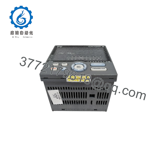
UP55A-001-11-00
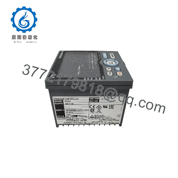
UP55A-001-11-00
Engineering Selection Highlights
- Standard Program Capacity → Supports up to 30 patterns and 300 total segments, suitable for multi-stage thermal profile applications without requiring high-capacity firmware expansions.
- Compact Enclosure Depth → Overall depth of 65 mm fits shallow mounting enclosures, operator panels, and OEM machine control boxes.
- Built-in Sequence Logic → Integrated ladder sequence control handles local digital I/O logic, alarms, and safety interlocks, eliminating the need for an external miniature PLC in basic systems.
- RS-485 Communication Included → Suffix
-1in the open network slot provides native 2-wire/4-wire RS-485 serial connectivity for Modbus RTU integration into SCADA systems or recorder networks. - Wide AC Line Operation → Accepts 100–240 V AC universal line input (+10% / -15%), allowing installation across global industrial grid voltages without external step-down transformers.
System Compatibility & Integration Requirements
| Item / Dependency | Verified Compatibility or Requirement | Practical Note |
| Mounting Cutout | Panel cutout size 92 mm × 92 mm (1/4 DIN format) | Mounts into standard 1/4 DIN panel cutouts using provided side mounting brackets. |
| Parameter Software | Yokogawa LL50A Parameter Setting Software | Connects via front optical interface cable or RS-485 network for pattern and parameter configuration. |
| Communication Protocol | Modbus RTU, Modbus ASCII, PC-Link, Ladder | RS-485 port connects directly to PLCs, HMI panels, paperless recorders, and industrial PCs. |
| Terminal Cover | Optional model UTAP001 | Provides IP20 touch-proof protective covering over rear screw terminals. |
| Power Supply Circuit | 100–240 V AC line power | Requires appropriate line fusing and external disconnect switch per local electrical codes. |
Dimensions, Mounting & Connection Notes
- Dimensions: Front bezel measures 96 mm (W) × 96 mm (H); overall depth behind panel is 65 mm.
- Mounting Method: Panel mounting via standard 92 mm × 92 mm square panel cutout. Securing brackets attach to top and bottom sides of the case.
- Environmental Limits: Operating temperature range from 0°C to 50°C; ambient operating humidity 20% to 90% RH (non-condensing).
- Wiring Terminals: Rear-panel M3 screw terminals for field wiring. Shielded twisted-pair cable is required for RS-485 serial communication runs.
- Clearance: Maintain adequate top and bottom panel ventilation spacing to prevent thermal buildup within panel enclosures.
FAQ
What is the Yokogawa -001-11-00?
The Yokogawa UP55A-001-11-00 is a 1/4 DIN panel-mounted program controller from the UTAdvanced series used for managing multi-segment process profiles and loop control.
How many program patterns and segments does the UP55A-001-11-00 support?
It supports up to 30 program patterns and 300 total program segments (up to 99 segments per pattern) as standard.
What power supply voltage is required for the UP55A-001-11-00?
The controller operates on a standard line voltage of 100–240 V AC (+10% / -15%) at 50/60 Hz.
What serial communication protocol does this specific model support?
The -1 in the open network suffix code indicates built-in RS-485 serial communication supporting Modbus RTU, Modbus ASCII, PC-Link, and ladder protocols at speeds up to 38.4 kbps.
Does the UP55A-001-11-00 have built-in logic capabilities?
Yes, it includes standard ladder sequence control capability executing up to 500 steps for handling local digital I/O logic and auxiliary equipment switching.
What are the panel dimensions and depth for the UP55A-001-11-00?
The controller features a 96 × 96 mm front panel bezel (1/4 DIN) and a compact enclosure depth of 65 mm behind the panel.
Verification & Troubleshooting Notes
- Display Unlit on Power-Up: Check primary line voltage across power terminals to verify 100–240 V AC supply voltage is present. Verify external panel line fuses or breakers are closed.
- Communication Failures (RS-485): Verify polarity of RS-485 (+) and (-) signal lines. Confirm communication parameters (station address, baud rate, parity, stop bits) set in controller parameters match the master PLC/HMI network settings. Ensure termination resistors (120 Ω) are placed at physical end-nodes.
- Input Error Indications (PV Flashing / Overrange): Verify input sensor wiring type matches parameter configuration (thermocouple, RTD, or DC voltage/current). Check thermocouple polarity and RTD lead-resistance balance across terminals.
- Digital Output Failure: Confirm external load voltage and current levels fall within discrete relay/transistor output contact ratings. Ensure common power return loops are established properly.