
 WhatsApp: +86 16626708626
 Email:
  Phone: +86 16626708626
Description
3. Key Technical Specifications
| Parameter | Value |
|---|---|
| Manufacturer | ABB |
| Model | GDC801B |
| Product ID | 3BHE024747R0101 |
| ABB Type Designation | GD C801 A101 |
| Product Type | Crowbar Driver PCB |
| Primary Function | Crowbar protection and drive control |
| Compatible Drive Families | ACS2000, selected ACS5000 Water-Cooled drives |
| Installation Location | Right cabinet control section (drive dependent) |
| PCB Type | Industrial multilayer PCB |
| Cooling | Cabinet air cooling |
| Mounting | Internal PCB mounting assembly |
| Net Weight | Approximately 0.74 kg |
| Spare Part Category | Medium-voltage drive spare part |
Engineering Note: ABB does not publicly publish detailed electrical characteristics, component-level schematics, or firmware data for this board. Always verify the hardware revision and associated drive documentation before installation.
4. Product Introduction
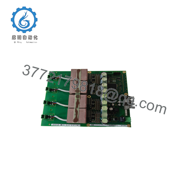
The ABB GDC801B (3BHE024747R0101) is a crowbar driver printed circuit board used in ABB medium-voltage AC drive systems, including the ACS2000 and selected ACS5000 platforms. The board controls the crowbar protection circuitry that safeguards the drive during abnormal operating conditions such as DC-link overvoltage or fault events.
From field experience, crowbar boards are typically replaced after protection circuit failures, insulation incidents, or major power-stage repairs. Since this board operates within the drive protection system, replacing it without confirming the correct hardware revision and firmware compatibility can result in startup faults or protection trips.

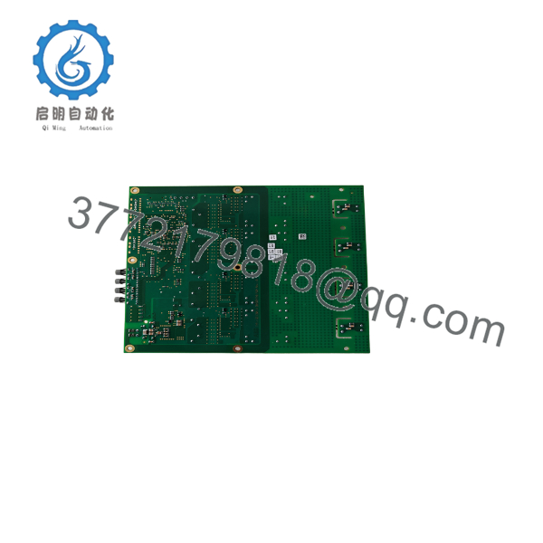
- GDC801B 3BHE024747R0101
- GDC801B 3BHE024747R0101
5. Installation & Configuration Guide
Stage 1 – Pre-Installation Preparation (Estimated Time: 20 Minutes)
⚠️ Safety First
- Notify plant operations before shutting down the drive.
- Stop the motor and isolate all incoming power.
- Apply Lockout/Tagout procedures.
- Wait at least 10 minutes for DC-link capacitors to discharge.
- Measure the DC bus with a calibrated multimeter before opening the cabinet.
Tools Required
- Grounded ESD wrist strap
- PH1 and PH2 screwdrivers
- Fluke 115 digital multimeter
- Insulated PCB extraction tool
- Camera or smartphone
Data Backup
Before removing the board:
- Record the drive firmware version.
- Save drive parameters using ABB Drive Composer or the applicable commissioning software.
- Photograph every connector.
- Label ribbon cables and fiber-optic cables.
- Record the hardware revision of the existing board.
Stage 2 – Removing the Old Board (Estimated Time: 15 Minutes)
- Verify zero voltage on the DC bus.
- Disconnect all ribbon and signal cables.
- Remove retaining screws.
- Slide the PCB straight out of its guide rails.
⚠️ Do not twist the PCB. Large industrial boards can develop cracked solder joints if flexed during removal.
Inspect:
- Backplane connector
- Edge contacts
- Burn marks
- Electrolytic capacitors
- Fiber-optic connectors (if equipped)
Keep the original board until the replacement has passed all operational tests.
Stage 3 – Installing the New Board (Estimated Time: 15 Minutes)
- Wear a grounded ESD wrist strap.
- Verify:
- Model: GDC801B
- Product ID: 3BHE024747R0101
- Install the board evenly into the guide rails.
- Tighten retaining hardware.
- Reconnect all cables according to the photographs taken during removal.
Configuration Check
Verify:
- Hardware revision
- Drive firmware compatibility
- Connector orientation
- Grounding points
- Cable routing
Self-Checklist
- ✅ Board fully seated
- ✅ All connectors secure
- ✅ Ground connections verified
- ✅ No bent pins
Stage 4 – Power-On & Testing (Estimated Time: 30 Minutes)
Pre-Power Inspection
- Verify insulation resistance where applicable.
- Check cabinet grounding.
- Confirm connector seating.
Startup Procedure
- Apply control power only.
- Observe board status indicators.
- Energize the drive.
- Monitor diagnostics for crowbar-related faults.
- Verify normal DC-link charging.
- Perform a no-load motor test before returning the drive to production.
⚠️ Troubleshooting Notes
Crowbar Fault After Replacement
The first item I check is the board revision. I’ve seen identical-looking boards with different hardware revisions that were not compatible with the installed drive firmware.
Drive Will Not Initialize
Inspect every ribbon cable and backplane connector. A partially seated connector can prevent the protection system from completing initialization.
Unexpected Protection Trips
Verify that the replacement board matches the exact product ID and the specific drive variant. Do not assume boards from different ACS2000 revisions are interchangeable.
6. Frequently Asked Questions (FAQ)
Q1. What is the purpose of the GDC801B?
The GDC801B is a crowbar driver PCB used within ABB medium-voltage drives. It controls the crowbar protection circuit, which helps protect the converter and DC-link during fault conditions.
Q2. Which ABB drive families use this board?
The board is documented as a spare part for the ACS2000 and is also listed for selected ACS5000 Water-Cooled drive systems. Always confirm compatibility using the drive serial number and spare parts manual.
Q3. Can I replace this PCB while the drive remains energized?
No.
Medium-voltage drives contain hazardous stored energy even after the incoming supply has been disconnected. Follow ABB’s discharge procedure and verify the DC-link voltage before touching any internal electronics.
Q4. What is the most common replacement mistake?
The most frequent issue is installing a board with the correct product ID but an incompatible hardware revision. I have seen maintenance teams spend an entire shift troubleshooting what appeared to be a communication fault, only to discover the replacement PCB was intended for a different drive revision.
Q5. Does replacing this board require firmware updates?
Not always, but it can. If the replacement PCB has a newer hardware revision, the drive firmware may also need updating. Compare the firmware version with ABB’s compatibility documentation before commissioning.
Q6. Is this board available as New Original or Refurbished?
Depending on inventory, suppliers typically offer:
- New Original
- New Surplus
- Refurbished (function tested)
For critical medium-voltage applications, request serial-number photographs, inspection reports, and functional test documentation before shipment.
Q7. What quality inspections should a supplier perform?
A qualified supplier should document:
- Inbound Inspection & Traceability
- OEM part number verification
- Serial number traceability
- Inspection for corrosion, repaired traces, damaged connectors, and component discoloration
- Functional Testing
- Installation in a compatible ABB medium-voltage drive test platform where available
- Power-on verification
- Protection circuit diagnostics
- Extended operational testing
- Test report with recorded results
- Electrical Testing
- Insulation resistance testing (where applicable)
- Ground continuity verification
- Visual inspection of solder joints and PCB integrity
- Hardware Verification
- Record the hardware revision
- Confirm compatibility with the intended drive family
- Final QC & Packaging
- QC sign-off
- ESD-safe packaging
- Heavy-duty protective carton
- QC inspection label with date
For medium-voltage drive electronics, documented testing and revision verification are considerably more valuable than a generic statement that the board has been “tested.”



