
 WhatsApp: +86 16626708626
 Email:
  Phone: +86 16626708626
Description
Key Technical Specifications
| Parameter | Value |
|---|---|
| Manufacturer | Allen-Bradley / Rockwell Automation |
| Manufacturer Part Number | 1336-SN-SP10A |
| Product Type | Inverter Snubber PCB / Renewal Part |
| Primary Function | Damps inverter switching transients and limits voltage stress in the power section |
| Drive Family | Allen-Bradley 1336 PLUS, 1336 PLUS II, 1336 FORCE, 1336 IMPACT, and 1336 REGEN |
| Named Drive Frame Application | 1336STEF |
| 460 V Drive Application | 150 to 250 HP |
| 575 V Drive Application | 150 to 300 HP |
| 575 V Frame Reference | A20 to A22, per Rockwell spare-parts documentation |
| Mounting Location | Internal VFD power section; chassis-mounted PCB assembly |
| Electrical Role | Inverter-side transient suppression; not a logic-control or I/O module |
| Replacement Status | Replaces an obsolete earlier inverter-snubber PCB in the Rockwell renewal-parts documentation |
| OEM Lifecycle Status | Discontinued by manufacturer |
| Handling Requirement | High-energy DC-bus equipment; qualified personnel, lockout/tagout, DC-bus discharge verification, and ESD protection required |
| Approximate Listed Weight | 1.50 lb, per a reseller record; verify shipping weight with the supplier |
Rockwell Automation’s 1336 spare-parts publication identifies 1336-SN-SP10A as an inverter snubber PCB for 1336STEF drives: 460 V, 150–250 HP; and 575 V, 150–300 HP, with the 575 V application referencing frames A20–A22. The same publication shows it as the replacement for an obsolete predecessor. Reseller records list the part as discontinued by the manufacturer.
Product Introduction
The Allen-Bradley 1336-SN-SP10A is an inverter snubber PCB used inside high-power 1336STEF adjustable-frequency drives. It controls switching transients in the inverter power section, helping protect the drive’s power semiconductors and associated components from voltage spikes generated during normal inverter operation.
This is a drive-specific renewal part, not a ControlLogix I/O module or a general-purpose control board. It must match the installed 1336 drive catalog number, voltage class, horsepower, power-frame arrangement, and original snubber-board location. For the documented application, use it only with compatible 460 V 150–250 HP or 575 V 150–300 HP 1336STEF drives.
Troubleshooting Quick Reference
| Symptom | Possible Cause | Relevance to this Part | Quick Check Method | Recommendation |
|---|---|---|---|---|
| Drive trips on inverter fault immediately after run command | Failed IGBT, shorted snubber component, gate-drive fault, output short, DC-bus fault | ✅ Medium to high | Record the exact 1336 fault code before resetting. Apply lockout/tagout, wait the OEM-specified discharge time, and verify zero DC-bus voltage at approved test points before internal inspection. | Do not replace the snubber board as the first guess. Check IGBTs, output cables, motor insulation, gate-drive boards, and DC bus first. |
| Drive trips only during fast acceleration or deceleration | High switching stress, braking issue, motor/load inertia, failing power device, degraded snubber circuit | ✅ Medium | Compare fault timing with acceleration/deceleration settings and motor load. Review DC-bus behavior and fault history using approved 1336 diagnostic procedures. | Check programmed ramps, braking hardware, motor load, and power devices. Replace the snubber only if testing identifies a defective snubber network. |
| Drive will not power up or has no display | Missing incoming power, blown control fuse, failed control power supply, open precharge circuit | ❌ Low | Verify incoming line voltage, control supply, fuses, and precharge status using the applicable 1336 service documentation. | The inverter snubber PCB is unlikely to cause a completely dead display. Repair the input or control-power problem first. |
| Repeated overcurrent faults with motor connected | Motor cable short, motor insulation failure, ground fault, failed IGBT module, incorrect motor data | ❌ Low to medium | Isolate the motor and test motor insulation with an appropriate megohmmeter per motor and drive procedures. Inspect output leads and compare drive behavior with the motor disconnected. | Check motor, cable, and IGBT health before replacing the snubber board. |
| Burn mark, cracked component, carbon tracking, or damaged PCB | IGBT failure, voltage transient, contamination, loose bus connection, external short | ✅ High | With DC bus verified discharged, inspect both sides of the board and nearby buswork under magnification. Check for loose hardware, discoloration, damaged capacitors/resistors, and contamination. | Replace the damaged board only after identifying the upstream cause. A failed IGBT or loose bus connection can destroy the replacement immediately. |
| Drive runs unloaded but faults under process load | Weak IGBT, motor/load issue, excessive current demand, degraded snubber circuit, poor cooling | ✅ Medium | Trend output current, heat-sink temperature, fault timing, and load condition. Compare with the drive’s rated operating envelope and inspect cooling fans and heat sinks. | Correct process overload and cooling issues first. Perform power-section troubleshooting before replacing the PCB. |
| Replacement snubber board does not fit or creates a fault | Wrong voltage class, wrong drive frame, incorrect part, damaged mounting hardware, incompatible assembly | ✅ High | Compare the old and replacement board labels, component layout, mounting holes, bus connections, and drive catalog number. Confirm the drive is 1336STEF and falls within the documented voltage/HP range. | Stop installation if anything differs. Do not drill, force, or modify the board to fit. |
| Drive faults after internal maintenance | Busbar hardware loose, connector not seated, phase lead swapped, missing insulation barrier, poor torque | ✅ Medium | Reinspect every internal connection against the 1336 power wiring and mechanical assembly documentation. Use the specified tightening torque; do not estimate. | Correct assembly errors before replacing another component. Photograph internal connections before disassembly. |
❗ High-voltage DC bus hazard: This board is installed in the power section of a large variable-frequency drive. Opening the disconnect does not guarantee the DC bus is safe. Follow the 1336 procedure, wait the required discharge time, and verify zero voltage with a properly rated meter before touching internal components.
❗ Do not diagnose by appearance alone: A snubber board can look clean while an IGBT or gate-drive circuit is the real fault. Conversely, a visibly damaged snubber board may be a result of an IGBT failure, not the initiating cause. Test the surrounding power section before installing a replacement.
❗ Match the drive frame and voltage class: Rockwell documents 1336-SN-SP10A for 1336STEF 460 V drives rated 150–250 HP and 575 V drives rated 150–300 HP. Do not apply it to a lower-horsepower, different-frame, or unrelated 1336 family drive based on physical similarity.
❗ Torque matters: Loose busbar or power-terminal connections create heat, arcing, and destructive voltage transients. Follow the OEM torque values, use the correct hardware, and reinstall all specified insulating barriers.
❗ ESD protection still applies: The board works in a high-power circuit, but it can still contain sensitive components. Wear a grounded wrist strap after the DC bus is safely discharged, and keep the replacement in ESD-safe packaging until installation.
Keep these checks in mind and you will save yourself 90% of typical rework time. If the fault remains unclear, send technical support the full 1336 drive nameplate, complete fault history, photos of the old board, IGBT test results, DC-bus readings, and motor-insulation test results.
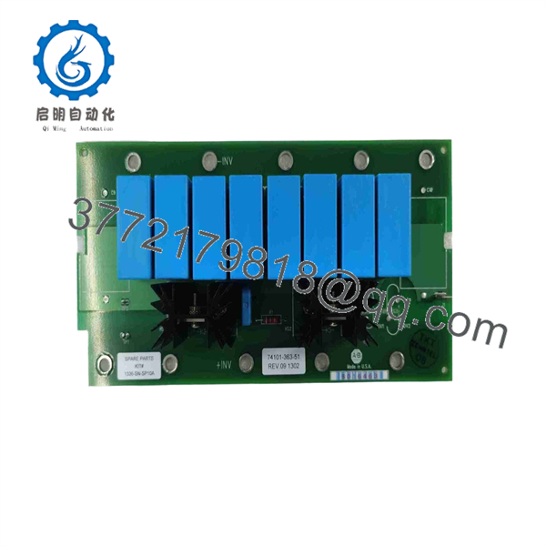
1336-SN-SP10A
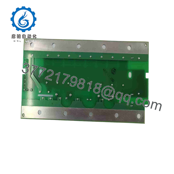
1336-SN-SP10A
Frequently Asked Questions
What is the Allen-Bradley 1336-SN-SP10A?
The 1336-SN-SP10A is an Allen-Bradley inverter snubber PCB used as a renewal part in compatible 1336STEF drives. Its function is to damp inverter switching transients in the power section. Rockwell lists it for 460 V 150–250 HP drives and 575 V 150–300 HP drives, with the latter referencing frame sizes A20–A22.
Is 1336-SN- a PLC I/O card or a drive control board?
No. It is an internal inverter snubber PCB for a 1336 variable-frequency drive power section. It does not replace a PLC I/O module, HIM, main control board, communications board, or a general-purpose motor controller. Its job is electrical transient suppression within the drive inverter.
Is this part compatible with every Allen-Bradley 1336 drive?
No. Rockwell’s spare-parts documentation ties it specifically to 1336STEF applications in defined voltage and horsepower ranges. Confirm the entire drive catalog number, input voltage, HP rating, frame, series letter, and original board part number before ordering. A compatible-looking snubber board may not have the required electrical rating or mounting pattern.
Can I install this board with the drive energized?
No. Never work on this part with the drive energized. Isolate all input power, follow site lockout/tagout procedures, wait the specified DC-bus discharge period, and measure the bus voltage at the approved points with properly rated test equipment. Large VFD DC buses can retain lethal energy after input power is removed.
How do I know whether the snubber board is actually defective?
Look for confirmed evidence: damaged snubber components, shorted or open components identified through qualified power-electronics testing, a fault that follows the board, or test results showing the inverter section is otherwise healthy. Before condemning the board, check IGBTs, gate drives, DC-bus capacitors, busbar torque, cooling, motor cables, motor insulation, braking hardware, and output shorts. In the field, these external or adjacent failures are more common than a snubber board failing by itself.
Does 1336-SN- replace an older board?
Yes. Rockwell’s 1336 spare-parts publication shows 1336-SN- as the replacement for an obsolete earlier inverter snubber PCB. Verify the exact original board reference and your drive frame before treating it as a direct field replacement.
Is 1336-SN- obsolete?
Yes. A reseller catalog identifies it as discontinued by the manufacturer, and it is normally sourced through New Surplus, unused legacy stock, tested used inventory, or qualified refurbishment channels. Confirm actual quantity, condition, photographs, lead time, warranty, and return terms before purchasing.
Why is a New Surplus snubber PCB less expensive than OEM service stock?
New Surplus parts often come from unused maintenance inventory, canceled projects, plant upgrades, warehouse liquidations, or drive-system decommissions. Lower price is acceptable only when the seller identifies the condition accurately and can show the complete label, component side, solder side, mounting hardware, packaging, and warranty terms. Avoid units described only as “untested pull” for a high-energy drive repair.
What inspection and test documentation should I request?
Request complete photos of the board label, both PCB sides, power connections, standoffs, and all high-energy components. Ask for inspection evidence covering cracked capacitors, failed resistors, heat damage, contamination, corrosion, damaged traces, rework marks, and bus-connection damage. For a tested unit, request documented component checks and, where a compatible fixture is available, insulation and controlled functional verification. A full live-drive test may not be practical or safe without the exact 1336 power frame; the supplier should disclose that limitation clearly.



