
 WhatsApp: +86 16626708626
 Email:
  Phone: +86 16626708626
Description
Key Technical Specifications
| Parameter | Specification Value |
|---|---|
| Catalog Number | 1756-L71 |
| User Data & Logic Memory | 2 MB |
| Non-Volatile Memory | Ships with 1 GB SD card (1784-SD1); supports up to 2 GB (1784-SD2) |
| Processor Family | ControlLogix 5571 |
| Communication Port | USB 2.0 Full Speed (12 Mbps, programming/maintenance port) |
| Energy Storage Module | Uses capacitor-based ESM (1756-ESMCAP or 1756-ESMNSE) instead of lithium batteries |
| Maximum Digital I/O | 128,000 inputs/outputs total |
| Maximum Analog I/O | 4,000 inputs/outputs total |
| Maximum Tasks | 32 tasks (1 continuous task + up to 31 periodic/event tasks) |
| Backplane Current (5.1V DC) | 800 mA |
| Backplane Current (24V DC) | 5 mA |
| Power Dissipation | 2.5 W max |
Product Introduction & Supply Chain Strategy
This product is a Brand New Surplus unit. It is not used, not pulled from a decommissioned plant, and not refurbished. All modules undergo rigorous quality verification to ensure OEM-level reliability. The Allen-Bradley 1756-L71 is the entry-level 2 MB processor in the ControlLogix 5570 (L7x) controller family. Designed for high performance and reduced maintenance, the 5570 series replaces legacy batteries with a maintenance-free Energy Storage Module (ESM) that saves active RAM contents to onboard non-volatile memory during unexpected power losses.
Sourcing the 1756-L71 as New Surplus offers a cost-effective path for upgrading legacy 1756-L55 or 1756-L61 systems. Upgrading to the L71 delivers a significant increase in processing speed and memory access efficiency while eliminating battery maintenance schedules. Additionally, because it integrates seamlessly into existing ControlLogix 1756 backplanes alongside current EtherNet/IP bridge cards (such as the 1756-EN2T), it enables performance modernizations without requiring chassis or power supply replacements.
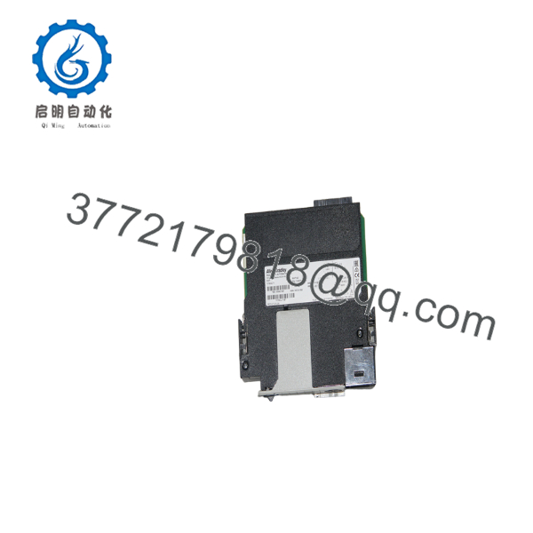
1756-L71
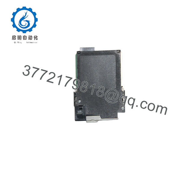
1756-L71
Installation & Configuration Guide
1
Stage 1: Pre-Installation (Prep & Safety)
Perform software backup, isolate rack power, and attach ESD wrist strap
1.Stage 1: Pre-Installation (Prep & Safety):Perform software backup, isolate rack power, and attach ESD wrist strap.
- Upload and verify a complete project backup (
.ACDfile) using Studio 5000 Logix Designer or RSLogix 5000 before removing the target controller. - Enforce strict Lock-Out/Tag-Out (LOTO) protocols on the ControlLogix chassis power supply.
- Wear a grounded Electrostatic Discharge (ESD) wrist strap attached to an unpainted metal surface on the enclosure panel.
- Verify that the Energy Storage Module (1756-ESMCAP or 1756-ESMNSE) and SD card (1784-SD1) are securely inserted into the front panel.
2
Stage 2: Removal
Set keyswitch to PROG, disconnect USB cable, and unlatch CPU
2.Stage 2: Removal:Set keyswitch to PROG, disconnect USB cable, and unlatch CPU.
- Turn the physical front-panel keyswitch to the
PROGposition. - Disconnect any USB programming cable connected to the front USB port.
- Depress the upper and lower module retention clips on the 1756-L71 housing.
- Slide the controller horizontally straight out of the chassis slot to protect the backplane pins.
3
Stage 3: Installation (Clone & Seat)
Align guide rails, seat controller, and secure retainers
3.Stage 3: Installation (Clone & Seat):Align guide rails, seat controller, and secure retainers.
- Align the top and bottom circuit board edges of the replacement 1756-L71 with the guide rails in the designated chassis slot.
- Push the controller firmly into the rack until both retention latches snap securely onto the chassis frame.
- Connect a USB programming cable or verify network communications through adjacent EtherNet/IP bridge modules (e.g., 1756-EN2T/EN3TR).
4
Stage 4: Power-On & Testing
Power up chassis, observe 4-character display, and download project
4.Stage 4: Power-On & Testing:Power up chassis, observe 4-character display, and download project.
- Re-apply power to the ControlLogix chassis power supply.
- Monitor the front 4-character alpha-numeric display and LEDs: confirm that the self-test completes and the display indicates the controller state.
- Open Studio 5000 Logix Designer (v20 through v36+), connect via USB or EtherNet/IP, match the controller firmware version, and download your project.
- Turn the keyswitch to
REMorRUNand verify that all remote I/O drops and network adapters transition to healthy states.
Firmware/Software Versions & Upgrade Notes
- Software Compatibility: Programmed using RSLogix 5000 (v20) and Studio 5000 Logix Designer (v21 through current releases).
- Battery-Free Operation: The 1756-L71 uses an Energy Storage Module (1756-ESMCAP standard, or 1756-ESMNSE removable for hazardous/secure applications) to write volatile memory to the SD card during power loss, eliminating the need for 1756-BA2 lithium batteries.
- Firmware Flashing: Firmware revisions can be updated easily via ControlFLASH or ControlFLASH Plus using the front-panel USB port or over EtherNet/IP.
- Non-Volatile Storage (SD Card): Ships with a 1784-SD1 (1 GB) Secure Digital card. Image load attributes (Load on Power-Up, Load on Corrupt Memory, User Initiated) can be set inside Studio 5000 under Controller Properties -> Non-Volatile Memory.
Frequently Asked Questions (FAQ)
What is the main difference between the 1756-L71, 1756-L72, and 1756-L73 controllers?
All ControlLogix 5570 controllers share identical processing speeds, ESM technology, and USB programming ports. The primary distinction is user memory capacity:
- 1756-L71: 2 MB User Memory
- 1756-L72: 4 MB User Memory
- 1756-L73: 8 MB User Memory
Does the 1756-L71 require a battery?
No. The 1756-L71 utilizes a capacitor-based Energy Storage Module (ESM) that provides short-term power upon system shutoff, long enough to write active RAM data onto the non-volatile SD card.
Can I replace a 1756-L61 with a 1756-L71?
Yes. Both controllers feature 2 MB of user memory. To upgrade, open your project file in Studio 5000 / RSLogix 5000, change the controller type from 1756-L61 to 1756-L71, update the firmware revision to match the new hardware, and download the project.
What is the purpose of the USB port on the front of the 1756-L71?
The USB 2.0 port is designed strictly for local programming, commissioning, online editing, and firmware flashing. It is not intended for permanent host computer networking or continuous data collection.
What warranty is included with this New Surplus controller?
We back this unit with a comprehensive 1-Year or 2-Year hardware replacement warranty (depending on your service agreement tier). If any hardware defect occurs during normal operation, an immediate replacement unit is dispatched directly from our buffer stock.



