
 WhatsApp: +86 16626708626
 Email:
  Phone: +86 16626708626
Description
3. Key Technical Specifications
| Parameter | Specification Value |
|---|---|
| Catalog Part Number | 1769-IQ16 |
| Manufacturer | Allen-Bradley (Rockwell Automation) |
| Compatible Architecture | CompactLogix Controllers & 1769 Expansion Racks |
| Number of Inputs | 16 discrete inputs (1 group of 16 points) |
| Voltage Category / Range | 24V DC nominal (10 to 30V DC operational range) |
| Input Type | Sinking or Sourcing (field wiring dependent) |
| On-State Current | 2.1 mA minimum @ 10V DC, 5.7 mA @ 24V DC |
| Off-State Current / Voltage | 1.5 mA maximum / 5V DC maximum |
| Backplane Current Draw | 115 mA @ 5.1V DC (0 mA @ 24V DC) |
| Power Distance Rating | 8 modules (maximum distance from 1769 power supply) |
| Hardware Delay Times | Off-to-On: 8 ms |
| Isolation Rating | 50V continuous (Group-to-Backplane optically isolated) |
| Terminal Block | 1769-RTBN18 (18-point fingerprint-safe terminal door) |
4. Product Introduction & Supply Chain Strategy
The Allen-Bradley 1769-IQ16 is a 16-point 24V DC discrete input module designed for CompactLogix control architectures and 1769 distributed expansion chassis. Utilizing optical isolation to protect backplane logic circuitry from industrial field noise, it interfaces reliably with field devices such as photoelectric eyes, selector switches, relay contacts, and proximity switches.
This product is a Brand New Surplus unit. It is not used, not pulled from a decommissioned plant, and not refurbished. All modules undergo rigorous quality verification to ensure OEM-level reliability.
Securing the 1769-IQ16 as New Surplus guarantees rapid field recovery during unplanned machine stoppages. Refurbished digital input cards often suffer from fatigued terminal block retention clips, cracked bus connectors, or degraded optocouplers that cause intermitted signal dropouts. Sourcing verified New Surplus provides original factory performance and physical integrity while bypassing extended lead times.
5. Installation & Configuration Guide
Stage 1: Pre-Installation (Prep & Safety)
- Open the incoming power disconnect feeding the CompactLogix system and apply Lock-Out/Tag-Out (LOTO).
- Wear an ESD wrist strap connected to cabinet frame ground before opening the module enclosure.
- Check the module Power Distance Rating (8): verify the 1769-IQ16 is mounted within 8 slots of its 1769 power supply.
- Verify field sensor power supplies deliver clean, regulated 24V DC power within the 10–30V DC operating window.
Stage 2: Removal
- Open the terminal block door and loosen the top and bottom retaining screws on the 1769-RTBN18 removable terminal block.
- Pull the removable terminal block assembly straight out from the module face.
- Unlock the top and bottom bus levers on adjacent modules to disengage the 1769 backplane bus connector.
- Unfasten DIN rail latch clips or mounting screws and slide the module off the DIN rail.
Stage 3: Installation (Clone & Seat)
- Mount the 1769-IQ16 onto the DIN rail adjacent to the neighboring 1769 module.
- Slide the module sideways until the tongue-and-groove bus connectors mesh fully.
- Lock the top and bottom bus levers securely to lock backplane communications into place.
- Press the pre-wired 1769-RTBN18 terminal block onto the front interface until the retaining screws engage.
Stage 4: Power-On & Testing
- Re-apply power to the 1769 power supply unit.
- Check the module status LEDs: the top
OKLED should illuminate solid green. - Open Studio 5000 Logix Designer / RSLogix 5000, verify the I/O configuration tree, and toggle field inputs to confirm LED indicator status matches ladder logic memory bits.
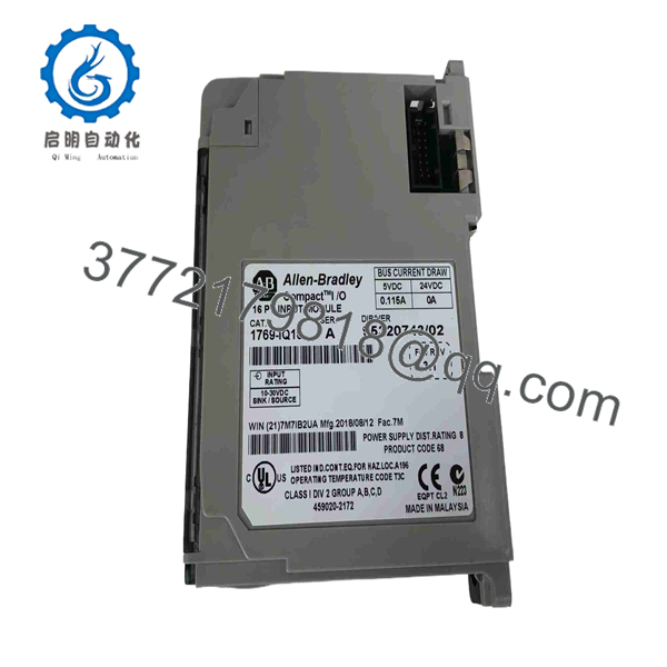
1769-IQ16
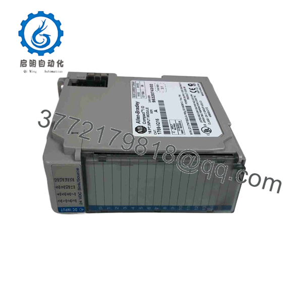
1769-IQ16
6. Firmware/Software Versions & Upgrade Notes
The 1769-IQ16 operates as a standard discrete input card and requires minimal software configuration.
- Studio 5000 / RSLogix 5000 Setup: Add the 1769- under the 1769 Bus configuration tree in Studio 5000. Electronic keying can be set to Compatible Module or Exact Match.
- Terminal Wiring: Supports both Sinking (connecting common to +24V DC) and Sourcing (connecting common to DC Common) field sensor configurations across all 16 channels simultaneously.
- Power Supply Calculation: Ensure total 5.1V DC backplane current consumption across all expanded 1769 modules does not exceed the current budget of the local 1769 power supply (e.g., 1769-PA2, PB2, PA4).
7. Frequently Asked Questions (FAQ)
Q: Is this 1769- module brand new or has it been pulled from a decommissioned machine?
A: This product is a Brand New Surplus unit. It is not used, not pulled from a decommissioned plant, and not refurbished. All modules undergo rigorous quality verification to ensure OEM-level reliability.
Q: What is the difference between 1769- and 1769-IQ32?
A: The 1769- provides 16 discrete 24V DC input points on an 18-pin removable terminal block, whereas the 1769-IQ32 provides 32 high-density 24V DC input points requiring 40-pin cable connections (1769-CBL).
Q: Can I use the 1769- with MicroLogix 1500 controllers?
A: Yes. The 1769 Compact I/O platform is compatible with both Allen-Bradley CompactLogix processors and MicroLogix 1500 expansion banks.
Q: Does the 1769- support individual channel isolation?
A: No. All 16 channels share a common return terminal, but the entire 16-point group is optically isolated from the CompactLogix backplane logic.
Q: What warranty applies to this New Surplus module?
A: We back this card with a full 1-year functional replacement warranty from the date of shipment, guaranteeing continuous machine uptime and zero risk.



