
 WhatsApp: +86 16626708626
 Email:
  Phone: +86 16626708626
Description
3. Key Technical Specifications
| Parameter | Value |
|---|---|
| Nominal Input Voltage | 120 V AC |
| Input Voltage Range | 97–132 V AC rms |
| Frequency | 47–63 Hz |
| Real Input Power (Max) | 59 W |
| Apparent Input Power (Max) | 89 VA |
| Backplane Output | 8 A @ +5 V DC |
| Module Width | 1 chassis slot |
| Fuse | 1.5 A, 250 V, slow-blow |
| Paralleling Cable | 1771-CT (for dual supplies up to 16 A) |
| Compatible Chassis | 1771-A1B, A2B, A3B, A4B and later |
| Operating Temperature | 0 to 60 °C (32 to 140 °F) |
| Storage Temperature | –40 to 85 °C (–40 to 185 °F) |
| Relative Humidity | 5 to 95% non-condensing |
| Weight (approx.) | 0.9 kg (2 lb) |
| Wire Size | 14 AWG max (single wire) |
| Terminal Block | 5-position (included, A-B 941274-05 or Wago equivalent) |
4. Product Introduction
The Allen-Bradley 1771-P4SB is a single-slot power supply module that delivers regulated 5 V DC at up to 8 A directly to the backplane of a 1771 I/O chassis. It accepts 120 V AC nominal input (97–132 V AC range) and is designed for PLC-5 systems using the universal 1771 chassis family.
This Series B version is the standard chassis-mounted supply used when external power supplies are not preferred. Two units can be paralleled with a 1771-CT cable to provide up to 16 A total backplane current. The module includes a front-panel status indicator and a replaceable slow-blow fuse for basic protection.
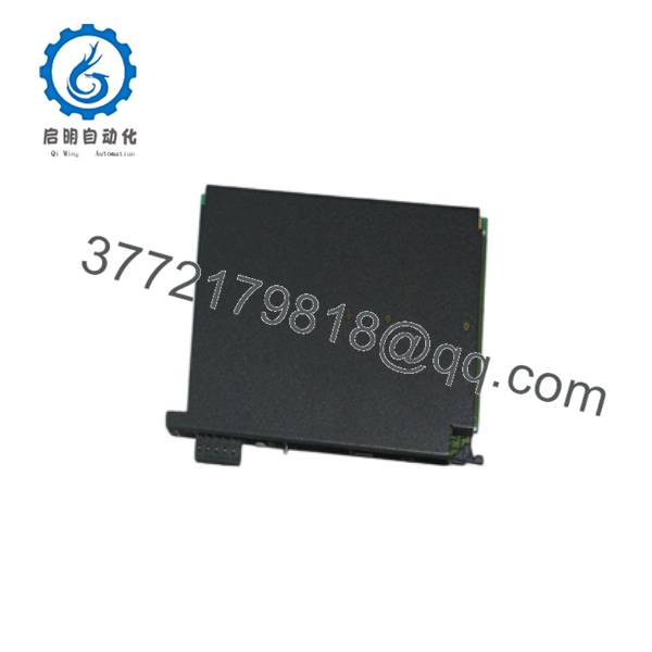
1771-P4SB
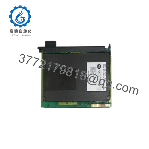
1771-P4SB
5. Installation & Configuration Guide
Stage 1: Pre-Installation Preparation (5–10 min) ⚠️ Safety First: Notify operations of downtime. Place the system in a safe state. Lock out/tag out the 120 V AC feed and any field power. Wait several minutes for residual energy to dissipate. Tools Required: ESD wrist strap, PH1 screwdriver, multimeter, wire labels, smartphone for photos. Data Backup: Photograph the existing power supply location, terminal wiring, fuse type, and any paralleling cable connections. Note total chassis current draw before removal.
Stage 2: Removing the Old Module (5–10 min)
- Confirm all AC power is removed from the supply and the chassis.
- Disconnect the 5-position terminal block (or individual wires) and label them.
- If paralleled, disconnect the 1771-CT cable.
- Release the module locking latch and pull the unit straight out of the chassis. Do not rock the module.
- Inspect the backplane connector for bent pins or contamination. ⚠️ Keep the old unit until the replacement is verified under load.
Stage 3: Installing the New Module (8–12 min)
- Verify the module is marked 1771-P4SB (Series B). Confirm the fuse is the correct 1.5 A slow-blow type.
- Align the circuit board with the chassis card guides and slide the module fully into the designated slot until it seats firmly in the backplane.
- Swing the locking latch down to secure the module.
- Reconnect the 120 V AC input (line, neutral, ground) to the terminal block using 14 AWG wire maximum. Torque terminals properly.
- If dual supplies are used, install the 1771-CT paralleling cable between the two units. Self-Checklist: [ ] Module fully seated [ ] Latch locked [ ] AC wiring correct and secure [ ] Fuse present and correct rating.
Stage 4: Power-On & Testing (10–15 min) Pre-Power Check: Verify no shorts on the AC terminals and correct polarity. Confirm chassis total current demand does not exceed 8 A (or 16 A if paralleled).
- Apply 120 V AC. Observe the front-panel “P/S ACTIVE” indicator — it should illuminate steady green.
- Measure backplane voltage at a convenient test point; it should read approximately 5.06 V DC (±3.8 %).
- Power up the processor and I/O modules. Monitor for any undervoltage or fault indications.
- If paralleled, verify both supplies share load and both indicators remain on. ⚠️ Troubleshooting Note: If the indicator stays off or the supply trips, check the fuse, input voltage range, and total chassis current draw. After a shutdown, wait at least 15 seconds before re-applying power.
6. Frequently Asked Questions (FAQ)
Q: Can the 1771-P4SB be hot-swapped? No. Removing or inserting the power supply with AC or backplane power present can damage the module or the chassis. Always isolate power first.
Q: Is the 1771-P4SB still in production? No. The entire PLC-5 / 1771 family is discontinued. Remaining units are new surplus or refurbished. Plan migration to ControlLogix (1756) power supplies when practical.
Q: What is the difference between 1771-P4S and 1771-P4SB? The “B” suffix denotes Series B hardware. Functionally they are interchangeable for most applications; always match the series when possible and verify any series-specific notes in the installation manual.
Q: Can I parallel two 1771-P4SB modules? Yes. Use the 1771-CT paralleling cable. Two supplies provide up to 16 A total backplane current. Both modules must be the same type and properly configured.
Q: Why is the price lower than historical OEM list price? These are genuine new surplus units from excess inventory. They have never been installed but are no longer supplied through standard Rockwell channels. Full functional testing and a warranty are provided.
Q: What fuse should I use? 1.5 A, 250 V slow-blow (Bussmann MDX1.5 or Littelfuse 31301.5 equivalent). Using a faster or higher-rated fuse defeats the protection and can damage the supply or chassis.
Q: Will replacing this power supply affect my PLC-5 program? No. The power supply only provides backplane voltage. Processor memory and logic remain intact provided the chassis remains powered long enough for an orderly shutdown or the program is battery-backed.



