
 WhatsApp: +86 16626708626
 Email:
  Phone: +86 16626708626
Description
Key Technical Specifications
| Parameter | Value |
|---|---|
| Product Model | DEIF FAS-113DG |
| Manufacturer | DEIF A/S |
| Product Category | Automatic Generator Synchroniser |
| Application | Generator-to-busbar synchronisation and breaker closing |
| Product Series | Uni-line |
| Mounting Method | 35 mm DIN rail or base mounting |
| Measuring Voltage Range | 57.7 to 690 V AC |
| Supply Voltage | 24-48-110-220 V DC or 57.7-690 V AC depending on variant |
| Frequency Range | 40 to 70 Hz |
| Breaker Closing Pulse | 400 ms ±10 ms |
| Voltage Difference Setting | ±2 to ±12 % of busbar voltage |
| Slip Frequency Range | 0.05 to 0.5 Hz |
| Operating Temperature | −25 to +70 °C |
| UL Listed Temperature Limit | Maximum 60 °C |
| Protection Rating | IP40 enclosure, IP20 terminals |
| Weight | Approximately 0.75 kg |
| Communication Interface | No digital fieldbus interface; relay and analog control outputs |
| Standards | IEC/EN 61000-6-1/2/3/4 EMC compliance |
Technical specifications are based on DEIF FAS-113DG documentation. Verify the exact variant before replacement because supply voltage and configuration options depend on the ordered version.
Product Introduction
The DEIF FAS-113DG is an automatic generator synchroniser from the Uni-line series, designed to synchronise a generator with a busbar and issue a circuit breaker closing command when voltage difference, slip frequency, and phase angle meet configured limits. It is commonly installed in generator control panels, switchboards, and power generation systems.
The module provides voltage control, breaker closing time compensation, LED status indication, and adjustable control pulses for different prime movers, including diesel engines and gas turbines. It is available in AC and DC supply variants.
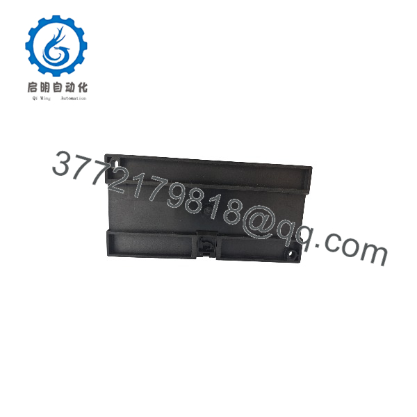
FAS-113DG
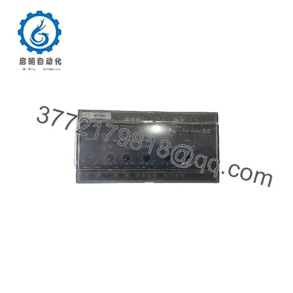
FAS-113DG
Installation & Configuration Guide
Stage 1: Pre-Installation Preparation (Approx. 10 minutes)
⚠️ Safety First
- Notify plant operations before removing the synchroniser from service.
- Verify the generator is in a safe operating condition.
- Apply lockout/tagout procedures to the control panel power supply.
- Wait at least 5 minutes for capacitor discharge before handling wiring.
Tools Required
- ESD wrist strap
- PH1 screwdriver
- Digital multimeter
- Wire labels
- Smartphone or camera for configuration records
Data Backup
Before removal:
- Record the FAS-113DG variant number and item number.
- Photograph all terminal wiring.
- Record voltage settings and frequency settings.
- Document relay output connections.
- Photograph front-panel adjustment settings.
Stage 2: Removing the Old Module (Approx. 10 minutes)
Steps
- Remove the transparent front cover carefully.
- Label every connected wire before disconnection.
- Loosen terminal screws and remove wiring without pulling on conductors.
- Release the DIN rail locking mechanism.
- Remove the module straight outward to avoid terminal and mounting damage.
- Inspect surrounding wiring, terminals, and mounting area.
⚠️ Note:
Keep the removed FAS-113DG until the replacement has completed commissioning. The old unit provides a reference for settings, wiring, and troubleshooting.
Stage 3: Installing the New Module (Approx. 10 minutes)
Steps
- Wear an ESD wrist strap before handling the replacement unit.
- Verify the replacement model and variant match the original unit.
- Configuration Clone (Critical):
- Copy all adjustment settings from the original module.
- Match voltage settings.
- Match frequency settings.
- Verify breaker closing parameters.
- Mount the module onto the DIN rail or base mounting position.
- Reconnect wiring using the correct terminal positions.
- Tighten terminals according to installation requirements.
Self-Checklist
- Correct FAS-113DG variant installed
- Voltage settings matched
- Frequency settings matched
- Relay wiring secured
- Mounting locked correctly
Stage 4: Power-On & Testing (Approx. 15 minutes)
Pre-Power Check
- Use a multimeter to confirm correct supply voltage.
- Check for accidental shorts between supply and ground.
- Verify terminal wiring against the original photographs.
Power-On Steps
- Energize the control panel.
- Observe LED indications.
- Confirm generator voltage and busbar voltage readings.
- Check synchronising status indication.
- Test breaker closing output logic.
- Perform a controlled synchronisation test.
⚠️ Troubleshooting Note
- If synchronisation does not occur, check voltage difference and frequency slip settings first.
- If the breaker command is incorrect, verify breaker closing time compensation settings.
- If readings are unstable, inspect voltage sensing wiring and grounding.
Frequently Asked Questions (FAQ)
Q1: Can the DEIF be hot-swapped while the panel is powered?
No. The is not designed for live insertion. Remove control power before disconnecting terminals. The synchroniser measures generator and busbar voltage signals, so incorrect removal under power can create unsafe switching conditions.
Q2: Is the DEIF obsolete?
The belongs to the DEIF Uni-line product family and is still documented by DEIF. Availability depends on inventory and regional supply channels. For older installations, confirm the exact variant number because AC and DC supply versions are different configurations.
Q3: What is the direct replacement if is unavailable?
The replacement depends on the generator control design. In some applications, engineers evaluate newer DEIF synchroniser models such as FAS-115DG, but replacement requires checking terminal layout, control philosophy, and required functions. Do not assume a direct plug-in replacement without reviewing drawings.
Q4: Will I lose generator synchronisation settings when replacing the module?
Yes, the stores its adjustment settings locally. Before removal, document all front-panel settings and terminal connections. A replacement unit must be configured to match the original operating parameters.
Q5: Why is a surplus usually priced below OEM list price?
Industrial automation spare parts are often sourced from discontinued projects, panel builders, excess inventory, or plant maintenance stock. Lower pricing does not automatically indicate a problem, but buyers should verify condition.
Available conditions normally include:
- New Original / New Surplus: unused inventory with original hardware condition
- Factory Sealed: unopened manufacturer packaging when available
- Refurbished (tested): inspected and function-tested units
Q6: What inspection process should be expected before purchasing a used or surplus ?
A professional inspection process should include:
1. Inbound Inspection & Traceability
- Verify source records and packing documentation.
- Check serial number markings.
- Inspect housing condition.
- Confirm no corrosion, scratches, repair marks, or contamination.
- Audit included accessories.
2. Functional Testing
- Power-up verification.
- LED status inspection.
- Voltage input simulation.
- Relay output testing.
- Synchronisation logic verification.
- Continuous operation monitoring.
3. Electrical Testing
- Insulation resistance testing using a 500 V Megger where applicable.
- Ground continuity verification.
4. Configuration Verification
- Record adjustment settings.
- Document hardware condition.
- Photograph configuration before shipment.
5. Final QC
- QC approval record.
- Anti-static packaging.
- Protective boxing.
- Test report available upon request.
Q7: What are the most common installation mistakes with replacement?
❗ Incorrect voltage configuration is the most common issue.
Engineers often replace a synchroniser without checking the original measuring voltage range or supply variant. A unit configured for a different voltage system may not synchronise correctly.
Other common problems:
- Incorrect generator/busbar voltage wiring.
- Wrong breaker closing output connection.
- Missing documentation of original settings.
- Incorrect frequency parameter adjustment.
I have seen generator commissioning delays caused by a five-minute documentation mistake during removal. Photograph the original settings before touching the terminals. That single step prevents a large amount of unnecessary troubleshooting.
Keep these checks in mind and you will avoid most replacement-related rework during generator control system maintenance.



