
 WhatsApp: +86 16626708626
 Email:
  Phone: +86 16626708626
Description
Key Technical Specifications
| Parameter | EPCPCRA |
|---|---|
| Product name | Embedded EPCPCRA Module |
| Brand | EMBEDDED |
| Model | EPCPCRA |
| Product category | Embedded industrial control module |
| Input voltage | 5–24 VDC reported by one source |
| Alternative supply listing | 24 VDC |
| Communication | CAN, Modbus RTU, RS-485, SPI, I²C reported |
| Processor | 32-bit ARM Cortex-M4 or similar reported |
| Digital I/O | 16 reported |
| Analog I/O | 8 reported |
| PWM | 4 channels reported |
| Relay outputs | 4 channels, 5 A/channel reported |
| Operating temperature | −40 to +85 °C reported |
| Mounting | DIN rail or wall mounting reported |
| Protection | Overvoltage, overcurrent, and ESD protection reported |
The specifications above come from secondary supplier listings, not an OEM technical manual. There are material inconsistencies between sources—for example, one listing gives 5–24 VDC while another gives 24 VDC, and reported memory specifications also differ. Therefore, these values should not be used as final engineering specifications without checking the physical unit, nameplate, drawings, or original documentation.
Product Introduction
The EMBEDDED EPCPCRA is listed as an embedded industrial control module intended for automation and equipment-control applications. Available supplier information associates the module with power control, signal processing, communication, and embedded control functions, including interfaces such as CAN, RS-485, Modbus RTU, SPI, and I²C.
For replacement applications, the exact hardware revision is important. Because publicly available documentation for the base EPCPCRA model is limited, the connector layout, supply requirements, firmware, I/O configuration, and mechanical dimensions should be checked against the installed unit before substitution.
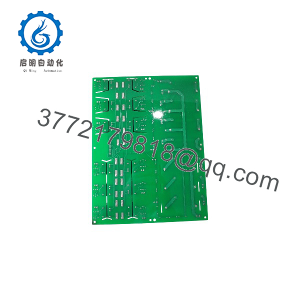
EPCPCRA
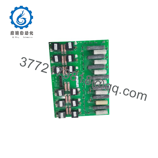
EPCPCRA
Installation & Configuration Guide
1. Pre-Installation
- ⚠️ Disconnect all external power sources and follow the machine’s lockout/tagout procedure.
- Record the complete EPCPCRA identification information, including PCB revision, serial number, and any additional suffix printed on the board.
- Photograph all connectors and wiring before removal.
- Verify the actual DC supply voltage from the system drawings and the original module.
- Check whether the application uses CAN, RS-485/Modbus, SPI, I²C, analog I/O, or relay outputs.
2. Remove the Existing Module
- Confirm that control and field power are isolated.
- Use ESD protection when handling the PCB.
- Label field wiring and communication cables if permanent labels are not already present.
- Disconnect connectors without pulling directly on individual wires.
- Inspect the removed board for configuration jumpers, switches, removable memory, or other application-specific hardware.
3. Install the Replacement
- Compare the replacement PCB with the original before installation.
- Verify connector positions, board revision, mounting holes, and terminal assignments.
- Install the module using the original mounting hardware.
- Reconnect communication and I/O wiring according to the approved wiring diagram.
- Confirm polarity for DC power, analog signals, and communication interfaces.
- ⚠️ Do not apply 24 VDC simply because it is listed by a supplier; confirm the actual voltage requirement of the specific hardware revision first.
4. Power-On and Testing
- Apply control power while keeping machine outputs and hazardous actuators inhibited.
- Check the module’s startup or diagnostic indicators.
- Verify communication with the host controller or supervisory system.
- Test digital inputs individually.
- Verify analog inputs using a calibrated signal source where applicable.
- Test relay and PWM outputs with the machine in a safe commissioning state.
- Confirm alarm, interlock, and emergency-stop circuits before returning the equipment to normal operation.
Troubleshooting priorities: If the module powers up but does not communicate, check supply polarity, communication wiring, address/termination settings, firmware compatibility, and connector pinout before replacing additional hardware.
Frequently Asked Questions (FAQ)
Q1. What is the EMBEDDED EPCPCRA?
It is listed by industrial automation suppliers as an embedded industrial control module used for control, communication, signal processing, and automation applications.
Q2. What communication interfaces are associated with EPCPCRA?
One supplier lists CAN, Modbus RTU, RS-485, SPI, and I²C. The actual interfaces available on a particular board should be confirmed from its PCB markings and documentation.
Q3. What is the EPCPCRA power supply?
Published secondary information is inconsistent. One source lists 5–24 VDC, while another lists 24 VDC. Do not select the power supply from a catalog listing alone; verify the actual board revision and electrical documentation.
Q4. Is EPCPCRA a GE Mark VIe module?
One supplier describes an “Embedded EPCPCRA” product as a protection module associated with GE Speedtronic Mark VIe systems, but this is not sufficient evidence to establish that the base EPCPCRA is an original GE Mark VIe component.
Q5. Is EPCPCRA interchangeable with EPCPCRA#136 B5?
It should not be assumed to be interchangeable. The web listings treat EPCPCRA and EPCPCRA#136 B5 as separate product identifiers. Hardware, I/O, firmware, and connector configurations should be compared before replacement.
Q6. Is the EPCPCRA obsolete?
I could not verify an official OEM lifecycle statement for the base EPCPCRA from the available sources. For procurement purposes, request the exact hardware revision and actual stock condition rather than assuming current production status.
Q7. What information should be provided when ordering EPCPCRA?
Provide EPCPCRA, a clear photograph of the board/nameplate, hardware revision, serial number if present, connector configuration, and the original equipment application. This is particularly important because public specifications for this model are inconsistent.



