
 WhatsApp: +86 16626708626
 Email:
  Phone: +86 16626708626
Description
3. Key Technical Specifications
| Parameter | Value |
|---|---|
| Model | 71G21K2L2-48P |
| Product Type | Managed Layer 2/Layer 3 Ethernet Switch |
| Access Ports | 48 × 10/100/1000Base-T RJ45 with IEEE 802.3af/802.3at PoE+ |
| High-Speed Uplinks | 2 × 1/10Gb SFP+ |
| Core Uplink Ports | 2 × 10/40Gb QSFP+ |
| Port Duplex | Full Duplex |
| Management Interfaces | CLI, Micro-USB, Console Port, SNMP |
| Stacking | Virtual Switch Bonding (VSB) Supported |
| Cabling | Category 5e or higher for RJ45 ports |
| Power Input | 100–240 VAC, 50/60 Hz |
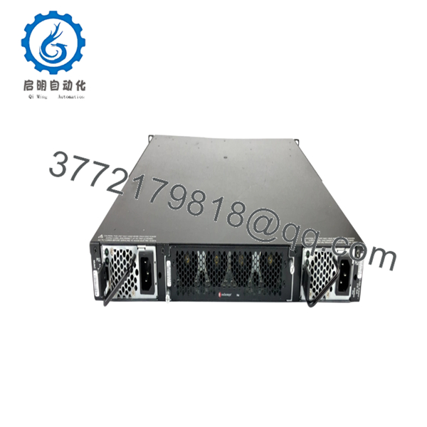
| Cooling | Hot-swappable fan modules |
| Compliance | IEEE 802.3, 802.3ab, 802.3af, 802.3at |
| Firmware | Verify firmware compatibility before deployment |
The dual QSFP+ interfaces can operate as native 40 Gb Ethernet uplinks or be configured as breakout 4 × 10 Gb interfaces. When configured for breakout mode, the dedicated SFP+ ports are unavailable. Verify the intended uplink configuration before commissioning.
4. Product Introduction
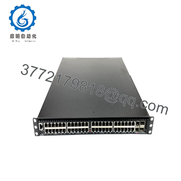
The Enterasys 71G21K2L2-48P is a member of the 7100G Series enterprise Ethernet switches designed for high-density campus aggregation, enterprise edge, and data center top-of-rack deployments. It combines forty-eight Gigabit PoE+ access ports with dedicated 10 Gb and 40 Gb uplinks to support bandwidth-intensive applications and modern network architectures.
From field experience, the 7100G platform remains a practical choice for organizations maintaining legacy Enterasys infrastructures. Its integrated PoE+, Virtual Switch Bonding (VSB), and flexible uplink architecture reduce the need for external aggregation switches while preserving compatibility with existing deployments.

- 71G21K2L2-48P
- 71G21K2L2-48P
5. Installation & Configuration Guide
Stage 1 – Pre-Installation Preparation (10 minutes)
⚠️ Safety First
- Notify network operations of the maintenance window.
- Confirm all affected services can tolerate downtime.
- Disconnect AC power and apply Lock-Out/Tag-Out procedures.
- Wait at least 5 minutes before removing hardware.
Tools Required
- Grounded ESD wrist strap
- PH1 screwdriver
- Fluke 115 (or equivalent) multimeter
- Cable identification labels
- Smartphone for documenting connections
Data Backup
- Save the running configuration.
- Export the startup configuration.
- Record management IP addresses.
- Photograph all copper and fiber connections.
- Record firmware version and license status.
Stage 2 – Removing the Existing Switch (10 minutes)
- Label every Ethernet and uplink cable.
- Remove QSFP+ and SFP+ transceivers carefully.
- Disconnect all network cables.
- Remove power cords.
- Unscrew the rack mounting hardware.
- Remove the switch while supporting its weight evenly.
⚠️ Keep the original switch available until the replacement has completed production testing successfully.
Stage 3 – Installing the Replacement (10–15 minutes)
- Wear a grounded ESD wrist strap.
- Verify the replacement model is exactly 71G21K2L2-48P.
- Install the switch into the rack.
- Secure all mounting screws.
- Install QSFP+ and SFP+ modules in their documented locations.
- Reconnect Ethernet cables.
- Restore redundant power supplies if fitted.
Self-Checklist
- ☑ Correct model verified
- ☑ Rack secured
- ☑ Fiber polarity confirmed
- ☑ Copper cabling restored
- ☑ Ground connection verified
Stage 4 – Power-On & Testing (15 minutes)
Pre-Power Check
- Verify AC voltage.
- Measure for shorts before energizing.
- Confirm all fan modules are properly installed.
Startup Procedure
- Apply AC power.
- Observe POST and LED indicators.
- Verify all cooling fans start normally.
- Connect through the console or Micro-USB interface.
- Confirm firmware revision.
- Restore the saved configuration if necessary.
- Verify PoE operation.
- Test SFP+ and QSFP+ uplinks.
- Confirm Virtual Switch Bonding status if deployed.
⚠️ Troubleshooting Notes
- Solid fault LED: Verify firmware compatibility with the existing network.
- No uplink on QSFP+: Confirm whether the ports are configured for native 40 Gb mode or breakout mode.
- SFP+ ports inactive: If QSFP+ ports are configured as four 10 Gb breakout interfaces, the dedicated SFP+ ports become unavailable. This behavior is normal and often catches engineers during upgrades.
Common Technical Pitfalls
❗ Firmware Revision Mismatch
I’ve seen maintenance teams replace a perfectly healthy switch only to spend hours troubleshooting because the replacement shipped with a newer EOS release. Record the original firmware before removal and request a compatible revision whenever possible.
❗ Uplink Mode Configuration
This is probably the most overlooked issue on the 7100G Series. The QSFP+ ports can operate either as native 40 Gb interfaces or as four 10 Gb breakout links. Those two modes directly affect SFP+ availability. Verify the configuration before assuming a hardware fault.
❗ Fiber Module Compatibility
Not every third-party SFP+ or QSFP+ optic is accepted. Verify supported transceiver types before installation to avoid intermittent link failures.
❗ PoE Power Planning
Forty-eight PoE+ ports can place a substantial load on the power subsystem. Calculate the expected power budget before connecting wireless access points, IP cameras, and VoIP phones simultaneously.
❗ Electrostatic Discharge (ESD)
Always use an ESD wrist strap and grounded work surface. I’ve watched engineers damage interface hardware before the switch ever reached the rack. It’s an expensive mistake that’s entirely preventable.
Keep these checks in mind and you’ll avoid most of the rework associated with 7100G Series deployments.
6. Frequently Asked Questions (FAQ)
Q1. Can I hot-swap the 71G21K2L2-48P?
No. This is a standalone switch, not a hot-swappable chassis module. Shut down the unit before replacing hardware to prevent data corruption or hardware damage.
Q2. Is the 71G21K2L2-48P discontinued?
Yes. The 7100G Series has been discontinued. Most available inventory today consists of unused surplus stock or professionally tested refurbished equipment.
Q3. Does it support both 10 Gb and 40 Gb uplinks?
Yes. The switch includes two dedicated 1/10 Gb SFP+ ports and two QSFP+ ports that support either native 40 Gb operation or breakout to four 10 Gb interfaces, depending on configuration.
Q4. Will replacing the switch erase my configuration?
No. Your saved configuration remains available if it has been backed up properly. Always export both the startup and running configurations before beginning maintenance.
Q5. Why is New Surplus hardware priced below the original OEM list?
The product has reached end of production, so pricing reflects secondary-market availability rather than the original manufacturer price. New Surplus units are unused inventory, while refurbished units have previously been deployed and tested.
Q6. How is each switch tested before shipment?
Every unit follows a documented inspection workflow:
- OEM identification and serial number verification
- Visual inspection for corrosion, connector wear, and repair marks
- Power-on self-test
- Management interface verification
- RJ45 port testing
- SFP+ and QSFP+ communication testing
- PoE functionality verification
- Firmware version documentation
- Final QC approval
- ESD-safe packaging with protective cushioning
Power-on videos, port test reports, and inspection photographs are available upon request.



