
 WhatsApp: +86 16626708626
 Email:
  Phone: +86 16626708626
Description
Key Technical Specifications
| Parameter | Specification |
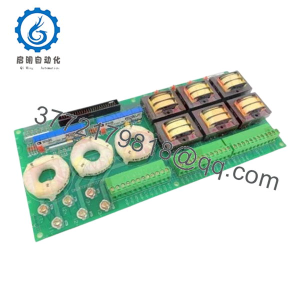
| Board Identifier | IPCS (Isolation Power Converter/Supply) |
| System Compatibility | GE Speedtronic Mark V (L-Frame / T-Frame) |
| Input Voltage | 125 VDC (Nominal) from System Bus |
| Output Channels | Multiple isolated DC outputs for Gate Drives |
| Isolation Rating | High-voltage galvanic isolation |
| Revision Level | G1A |
| Cooling | Natural Convection |
| Mounting | Stand-off mounting within the Power Distribution Core |
| Fusing | Onboard high-speed protection fuses |
Product Introduction
The GE DS200IPCSG1A is a critical Isolation Power Converter Supply (IPCS) board utilized within the GE Speedtronic Mark V control system. Its primary role is to provide isolated DC power to the silicon-controlled rectifier (SCR) gate drive circuits. By isolating the control logic from the high-power switching environment of the turbine’s exciter or static starter, the IPCS protects sensitive microprocessors from catastrophic electrical noise and voltage spikes.
This board is essential for maintaining the “dirty” power side of the Mark V cabinet. The G1A revision features a robust transformer-isolated design capable of withstanding the harsh electrical transients common in heavy industrial environments. For plant operators maintaining aging Mark V fleets, the DS200IPCSG1A is a high-priority spare, as failure in this module directly results in the loss of SCR firing capability, leading to an immediate unit trip.

- DS200IPCSG1A
Installation & Configuration Guide
Stage 1: Pre-Installation Preparation (Estimated Time: 15 mins)
- ⚠️ Safety First: The IPCS board handles 125 VDC bus power and is connected to high-current SCR circuits. Ensure the main DC distribution breakers are open. Discharge all large capacitors in the power core before touching the board.
- Tools Required: Insulated nut driver set, digital multimeter (DMM) rated for 600V, and an ESD wrist strap.
- Circuit Verification: Use your DMM to verify that the 125 VDC input leads are truly dead. Residual charge in the system can be lethal or easily fry the new board.
Stage 2: Removing the Old Module
- Label all plug-in connectors (e.g., J1, J2, PL). These carry the isolated power to the various gate drive boards.
- Carefully unplug the ribbon cables and power leads. Do not pull on the wires; use the connector housings.
- Unscrew the mounting hardware from the stand-offs.
- Inspect the area for “sooting” or carbon tracking. If the old board failed due to an arc-over, you must clean the mounting area with an approved electronics cleaner before installing the new unit.
Stage 3: Installing the New Module (Estimated Time: 20 mins)
- Fuse Check: Verify that the onboard fuses on the new DS200IPCSG1A match the ratings specified in your Mark V cabinet’s BOM.
- Align the board with the stand-offs and secure the mounting screws. Ensure the board is level and not touching the metal chassis.
- Reconnect the power and interface cables. Ensure connectors are keyed correctly. Forcing a connector upside down on this board will result in a short circuit across the 125V bus.
- Self-Checklist: [ ] Fuses verified, [ ] Stand-offs secure, [ ] All “J” and “PL” connectors seated.
Stage 4: Power-On & Testing
- Close the logic power breakers first to verify the rest of the rack initializes.
- Close the 125 VDC supply breaker to the IPCS board.
- Check the diagnostic LEDs on the board (if applicable) or monitor the Mark V “I” core diagnostics.
- Verify the output voltages at the test points (typically +/- 15V or 24V isolated nodes) using your DMM. If voltages are outside +/- 5% of nominal, check the input bus stability.
Frequently Asked Questions (FAQ)
Q: Can I replace a DS200IPCSG1A with a “G1B” or “G2A” revision?
A: Generally, yes. In the Mark V system, “G” (Group) revisions are usually backward compatible. However, if moving from a G1 to a G2, check for physical footprint changes or different connector styles. The G1A is the standard replacement for most 125V isolation applications.
Q: Why did my IPCS board fuses blow immediately after installation?
A: This is usually caused by a downstream short in one of the SCR gate drive boards or the cabling. The IPCS is a power provider; if the “load” it is feeding is shorted, the fuses will clear to protect the 125V DC bus. Test your gate drive cables for shorts to ground before replacing the fuses.
Q: Is it okay to use a refurbished board instead of this “New Surplus” one?
A: I don’t recommend it for power supply boards. Refurbished IPCS boards often have aged transformers and capacitors that have been baked by years of heat. A “New Surplus” board has zero “on-time,” meaning the dielectric strength of the insulation is significantly higher, which is critical for an isolation board.
Q: Does this board require any software configuration in TCI or CV?
A: No. The DS200IPCSG1A is a “dumb” power supply in terms of software. It does not have a processor and does not require a firmware download. It simply needs correct physical installation and input power.
Q: What is the typical lifespan of these boards?
A: In a clean, temperature-controlled environment, these can last 20 years. However, in hot or humid cabinets, the electrolytic capacitors typically start to drift after 10–12 years. If you see bulging caps or hear a high-pitched whine (transformer singing), it’s time to swap it out.


