
 WhatsApp: +86 16626708626
 Email:
  Phone: +86 16626708626
Description
3. Key Technical Specifications
| Parameter | Value |
|---|---|
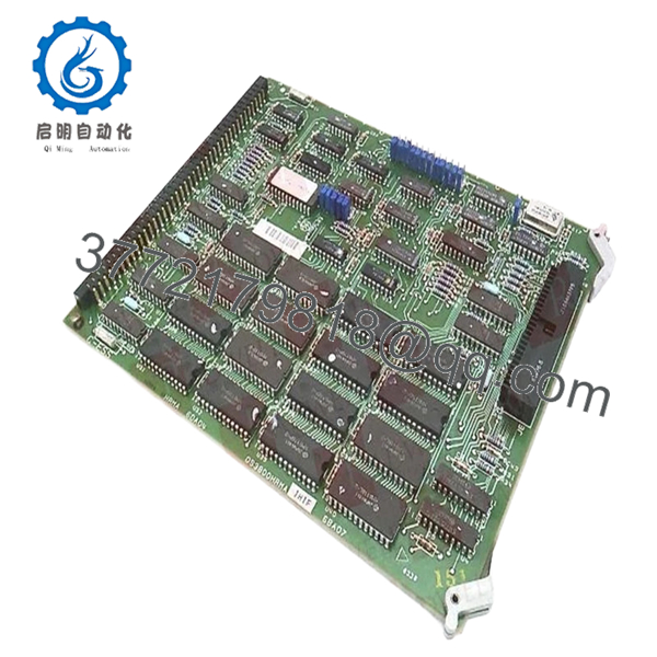
| Manufacturer | General Electric |
| Model Number | DS3800HRMA1H1F |
| Product Series | Speedtronic Mark IV DS3800 |
| Board Type | RAM Memory Board |
| Application | Turbine control memory and data handling |
| Memory Architecture | Dual-port RAM structure |
| Interface Method | Mark IV backplane edge connector |
| Mounting Method | Rack-mounted PCB with retention levers |
| PCB Coating | Industrial conformal coating |
| System Compatibility | GE Mark IV turbine control systems |
| Diagnostic Features | LED indicators and jumper-configurable logic |
| Connector Style | Modular connector interface |
| Typical Environment | Industrial turbine control cabinet |
| Handling Requirement | ESD-safe handling mandatory |
| Approximate Weight | 0.4–0.8 kg |
| Operating Temperature | Typically 0 °C to 70 °C cabinet ambient |
The DS3800HRMA1H1F functions as a memory and data buffering board within GE Mark IV Speedtronic turbine control systems. Exact memory configuration and jumper behavior should be verified against the installed Mark IV cabinet documentation before replacement.
4. Product Introduction
The GE DS3800HRMA1H1F is a RAM Memory Board used in GE Speedtronic Mark IV turbine control systems. The board supports temporary data storage, memory buffering, and communication handling between Mark IV processing sections and associated control subsystems.
In real-world turbine cabinets, memory-related DS3800 boards are often treated as critical spares because intermittent RAM faults can produce startup inhibits, watchdog trips, or unstable communication behavior that is difficult to diagnose during an outage window. Many facilities still operating Mark IV hardware prefer direct board replacement instead of a full controls retrofit.
5. Installation & Configuration Guide
Stage 1: Pre-Installation Preparation (Estimated Time: 10–15 Minutes)
⚠️ Safety First
- Notify operations before shutdown.
- Verify the turbine is in a safe shutdown condition.
- Apply lock out/tag out procedures.
- Wait at least 5 minutes for cabinet capacitor discharge.
- Verify zero voltage using a calibrated Fluke 115 multimeter.
Older Mark IV power supplies do not always discharge evenly. Never trust indicator lamps alone.
Tools Required
- Grounded ESD wrist strap
- PH1 screwdriver
- Fluke 115 multimeter
- Smartphone for documentation photos
- Wire labels
- ESD-safe work surface
- Flashlight for cabinet inspection
Data Backup
- Record cabinet slot location.
- Export controller configuration if accessible.
- Photograph:
- Jumper settings
- Connector orientation
- Ribbon cable routing
- Grounding straps
- Label all disconnected cables.
⚠️ Memory boards are notorious for “almost working” after replacement. One incorrect jumper can create intermittent faults that only appear during startup sequencing.
Stage 2: Removing the Old Module (Estimated Time: 5–10 Minutes)
- Remove the cabinet access cover.
- Label and disconnect all ribbon and signal connectors carefully.
- Release retention levers evenly.
- Remove mounting hardware if present.
- Pull the board straight outward to protect edge connectors.
- Inspect:
- Bent pins
- Connector oxidation
- Dust contamination
- Heat discoloration
- Cracked solder joints
⚠️ Important: Keep the original board available until the replacement passes full runtime testing.
I’ve watched technicians discard the old board too early, only to realize the replacement revision used different jumper defaults and memory addressing behavior.
Stage 3: Installing the New Module (Estimated Time: 10 Minutes)
- Wear the grounded ESD strap before touching the PCB.
- Verify exact model:
- DS3800HRMA1H1F
- Compare revision labels carefully.
Configuration Clone (Crucial)
Replicate:
- Jumper positions
- Addressing configuration
- Connector orientation
- Shield grounding layout
⚠️ This is one of the most common mistakes during Mark IV board replacement. If the memory addressing jumpers do not match, the controller may throw watchdog faults or fail initialization entirely.
- Insert the board evenly into rack guides.
- Lock retention levers completely.
- Reconnect all cables carefully.
Self-Checklist
- Model numbers match
- Jumper settings duplicated
- Connectors fully seated
- Retention levers locked
- Grounding verified
- No loose hardware in cabinet
Stage 4: Power-On & Testing (Estimated Time: 15–20 Minutes)
Pre-Power Check
- Verify no short exists on the 24 V rail.
- Confirm cabinet grounding continuity.
- Inspect edge connector seating carefully.
Power-On Sequence
- Energize the control rack first.
- Observe LED startup behavior.
- Verify controller initialization completes normally.
- Connect engineering workstation if available.
- Monitor communication stability and memory diagnostics.
- Perform dry-run testing before enabling field operation.
Functional Verification
Check:
- Stable controller startup
- No watchdog alarms
- No memory parity faults
- Stable communication between processing sections
- No intermittent resets
Memory-related faults in Mark IV systems can appear random at first. In reality, most trace back to poor connector seating, ESD damage, or incorrect jumper configuration.
⚠️ Troubleshooting Note
If the controller fails initialization after replacement:
- First suspect jumper mismatch.
- Second inspect connector seating.
- Third verify revision compatibility.
I once watched a startup crew spend nearly eight hours troubleshooting “processor instability” after a memory board replacement. The actual problem was one addressing jumper left in the factory default position.
Technical Pitfall & Survival Guide
❗ Firmware and Revision Compatibility
Mark IV memory boards are not universally interchangeable.
Avoidance:
Document the full suffix and revision markings before ordering.
I’ve seen systems boot partially, then fail under runtime load because the replacement revision handled memory timing differently.
❗ Jumper Misconfiguration
Memory addressing jumpers must match the original board exactly.
Avoidance:
Photograph every jumper before removal and duplicate settings precisely.
Do not assume factory defaults are correct.
❗ Connector Seating Problems
Edge connectors on older Mark IV racks wear over time.
Avoidance:
Insert the board straight and lock retention levers fully.
A partially seated memory board creates intermittent watchdog trips that can waste an entire outage shift.
❗ Power Supply Margin Issues
Aging Mark IV cabinets often operate close to PSU limits.
Avoidance:
Verify rack supply stability and maintain at least 20% current margin.
Unstable supply rails can mimic RAM failures.
❗ Electrostatic Discharge (ESD)
Memory ICs are highly vulnerable to static discharge.
Avoidance:
Use grounded wrist straps and ESD-safe surfaces at all times.
I once watched an engineer unpack a replacement RAM board during winter without grounding himself. The board booted initially, then failed permanently after twenty minutes of runtime. Static damage. Expensive lesson.
Keep these checks in mind and you’ll save yourself 90% of typical rework time.

- DS3800HRMA1H1F
6. Frequently Asked Questions (FAQ)
Q1: Can I hot-swap the DS3800HRMA1H1F?
No.
The GE Mark IV platform was not designed for live insertion of memory boards. Hot-swapping can corrupt memory states, damage the backplane, or trigger watchdog trips.
Always power the cabinet down completely first.
Q2: Is the DS3800HRMA1H1F obsolete?
Yes.
This board belongs to the GE Mark IV legacy platform. Most inventory available today comes from:
- New surplus stock
- Plant spare inventories
- Professionally refurbished units
Factory-sealed inventory still exists but quantities are increasingly limited worldwide.
Q3: What does this board actually do?
The DS3800HRMA1H1F handles:
- Temporary memory storage
- Data buffering
- Internal communication support
- Memory exchange between processing sections
A failed memory board can create startup faults, intermittent resets, or communication instability.
Q4: Will replacing this board erase turbine logic?
Usually no.
Primary turbine application logic normally resides in the main Mark IV processor architecture, not directly on the RAM interface board.
However, jumper settings and memory addressing still matter greatly.
Q5: Why are some surplus units priced much lower than others?
Usually because of:
- Unknown test status
- Missing traceability
- Cosmetic damage
- Untested pull inventory
- Refurbished boards sold unclearly
Always request:
- Serial photos
- Runtime test reports
- Connector close-up photos
- QC documentation
- Packaging verification
A serious supplier should provide them without hesitation.
Q6: What should I verify before ordering?
At minimum verify:
- Exact model number
- Full suffix revision
- Jumper configuration
- Cabinet slot assignment
- Existing Mark IV revision level
- Connector condition
Even visually similar DS3800 boards may not be electrically interchangeable.
Q7: What testing should a supplier perform before shipment?
Minimum acceptable QC should include:
- Visual PCB inspection
- Connector integrity inspection
- Insulation resistance testing (>10 MΩ preferred)
- Controlled power-up testing
- Memory diagnostics verification
- 24-hour runtime testing
- ESD-safe packaging and sealing
Good suppliers should also provide:
- QC photos
- Runtime verification reports
- Test videos
- Packaging photos before shipment
A memory board tested under live Mark IV rack conditions means substantially more than a simple “power-on tested” label.


