
 WhatsApp: +86 16626708626
 Email:
  Phone: +86 16626708626
Description
3. Key Technical Specifications
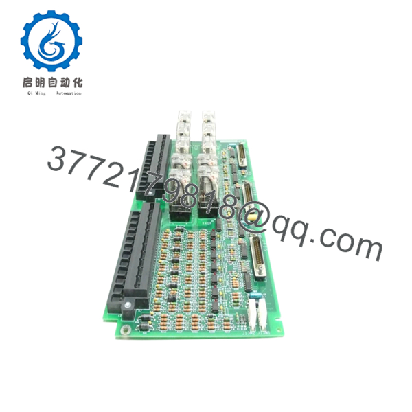
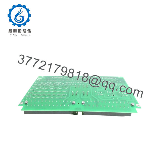
IS200ECTBG1ABB is identified as an Excitation Contact Terminal Board used in GE Mark VI turbine control systems and EX2100 excitation environments. The board operates only in redundant mode and interfaces through the EMIO board.
| Parameter | Value |
|---|---|
| Manufacturer | GE General Electric |
| Model | IS200ECTBG1ABB |
| Functional Acronym | ECTB |
| Product Type | Excitation Contact Terminal Board |
| Series | Mark VI IS200 |
| System Architecture | Redundant mode only |
| Relay Outputs | 4 Form-C contact outputs |
| Trip Outputs | 2 customer lockout trip outputs |
| Auxiliary Inputs | 6 |
| Input Power | 70 VDC for 52G and 86G inputs |
| Power Sources | M1 and M2 redundant supplies |
| Controlled By | EMIO board |
| Compatible Boards | EPCT, EXTB, EACF |
| Instruction Manuals | GEI-100457 / GEH-6632 |
| Dimensions | Approx. 33 × 10.2 × 4.8 cm |
| Warranty | Typically 12 months |
The 52G input monitors generator online status while the 86G input functions as lockout monitoring.
4. Product Introduction
GE IS200ECTBG1ABB is an Excitation Contact Terminal Board used in GE Mark VI turbine control and EX2100 excitation systems. It handles excitation-related contact inputs and outputs and interfaces through the EMIO architecture for generator control applications in gas, steam, and wind turbine systems.
In field deployments, ECTB boards are usually installed where excitation logic and lockout status signals interact with generator protection functions. Engineers typically insist on exact suffix matching because hardware revision changes in Mark VI systems occasionally create startup faults that are difficult to diagnose. I’ve seen this happen during outage windows when every hour matters.
5. Installation & Configuration Guide
Stage 1: Pre-Installation Preparation (Estimated: 10 minutes)
⚠️ Safety First: Notify operations personnel of scheduled downtime. Confirm the turbine is in a safe state. Apply lockout/tagout procedures. Wait at least 5 minutes for discharge of cabinet power systems.
Tools Required
- ESD wrist strap
- PH1 screwdriver
- Fluke 115 multimeter
- Wire labels
- Smartphone for photos
- ESD work mat
- Flashlight
Data Backup
- Export Mark VI or EX2100 configuration data.
- Record cabinet and slot location.
- Photograph all field wiring.
- Photograph DIP settings and jumpers.
- Record EMIO and I/O addressing.
⚠️ On older turbine cabinets, undocumented modifications are common. Never assume original drawings reflect actual field wiring.
Stage 2: Removing the Old Module (Estimated: 5 minutes)
- Remove cabinet access covers.
- Label each terminal and connector.
- Disconnect wiring carefully.
- Release retention hardware.
- Pull board straight out.
Inspect:
- Backplane connector condition
- Bent pins
- Dust buildup
- Heat discoloration
⚠️ Keep the removed board nearby until startup is complete.
I’ve watched teams ship failed boards immediately for repair and later discover jumper positions were never documented.
Stage 3: Installing the New Module (Estimated: 10 minutes)
- Wear ESD protection.
- Verify exact model number: IS200ECTBG1ABB
- Configuration Clone (Crucial): Copy all switch and jumper settings exactly.
Pay attention to:
- Node configuration
- Termination settings
- Hardware jumpers
- Redundant wiring selections
This is the most common rookie mistake, but it happens constantly. Take a picture before you pull it. I can’t stress this enough.
- Insert board slowly.
- Confirm complete seating.
- Reconnect field wiring.
Self-Checklist
- DIPs match
- Wiring secured
- Lock tabs engaged
Stage 4: Power-On & Testing (Estimated: 10 minutes)
Pre-Power Check
Use a multimeter to check for shorts on control power rails.
Power-up sequence:
- Energize rack only
- Observe LEDs
- Verify communications
- Connect engineering workstation
- Confirm EMIO interaction
- Verify contact status operation
LED review:
- Green RUN = expected operation
- Red ERR = investigate fault condition
⚠️ Troubleshooting Note: Solid fault indicators after startup often indicate firmware or board revision mismatch.
I once saw a project where a technician swapped in a newer board revision. The controller generated communication timeout alarms for two days before anyone checked firmware history.
SOP Quality Transparency
Inbound Inspection & Traceability
- Verify OEM packaging records and serial numbers.
- Perform anti-counterfeit checks.
- Inspect labels and holograms.
- Check for corrosion, rework marks, scratches, and UV discoloration.
- Verify manuals and supporting documentation.
Live Functional Testing
Testing performed on a GE-compatible Mark VI rack where available. Test procedures include:
- Power-on verification
- LED sequence inspection
- Communication handshake testing
- Input/output simulation
- Continuous operation exceeding 24 hours
- Thermal monitoring
Official test reports generated afterward.
Electrical Parameter Testing
- 500 V Megger insulation resistance >10 MΩ
- Ground continuity check
- Hipot testing where applicable
Firmware & Configuration Verification
- Record firmware revision
- Document jumper positions
- Create photographic records
Final QC & Packaging
- QC sign-off
- ESD anti-static packaging
- Bubble wrap protection
- Heavy-duty carton
- QC label with inspection date
Test photos and videos are available upon request.
Technical Pitfall & Survival Guide
❗ Firmware Revision Mismatch
Document old firmware before pulling the board.
I’ve seen replacements move between revision families and trigger communication timeout alarms for two days.
❗ DIP Switch Errors
Take photos before touching anything.
Simple issue. Happens constantly.
❗ Terminal Block Assumptions
Even similar Mark VI boards can change terminal definitions.
Do not wire from memory.
❗ Power Draw Requirements
Calculate cabinet loading and maintain at least 20% capacity margin.
Additional I/O boards add up faster than many engineers expect.
❗ ESD Damage
Wear a grounded wrist strap.
I watched an engineer handle a board in winter without protection. Powered up the cabinet and smoke appeared instantly. Thousands of dollars disappeared in ten seconds.
Keep these checks in mind and you’ll save yourself 90% of typical rework time.

- IS200ECTBG1ABB
- IS200ECTBG1ABB
6. Frequently Asked Questions (FAQ)
Q1: Can I hot-swap this module?
No.
IS200ECTBG1ABB is not designed for hot replacement. Pulling it under power risks backplane damage and can create excitation faults. Shut the cabinet down first.
Q2: Is IS200ECTBG1ABB obsolete?
Yes.
The board belongs to GE’s Mark VI generation. Current availability largely depends on surplus inventory and specialty industrial stock channels.
Q3: Is this actually new or refurbished?
Depends on stock source.
New Surplus generally means unused inventory from older projects. Refurbished units were previously deployed and tested. Request test reports and actual photos.
Q4: What is the direct replacement if this board is unavailable?
Stay with exact revision matching whenever possible.
IS200ECTBG1ABB operates within redundant excitation architecture and interacts with EMIO-managed functions. Verify compatibility before substitution.
Q5: Will I lose controller logic during replacement?
Usually no.
Logic normally resides elsewhere in the Mark VI controller architecture. Still, always back up configuration before removing hardware.
Q6: Why is surplus pricing lower than OEM factory pricing?
Inventory age.
Most suppliers purchased stock years ago and are distributing remaining inventory. Lower pricing does not automatically mean lower quality.
Q7: What boards interact with IS200ECTBG1ABB?
The board works with EPCT, EXTB, EACF, and EMIO-related architectures in redundant excitation systems. Verify exact configuration against OEM documentation before installation.


