
 WhatsApp: +86 16626708626
 Email:
  Phone: +86 16626708626
Description
Key Technical Specifications
| Parameter | Specification |
| Model Code | H4135A |
| HIMA Part Number | 992413560 |
| Nominal Operating Voltage (U_n) | 24 VDC |
| Coil Power Consumption | ~40 mA low-power actuation |
| Contact Isolation | High dielectric galvanic isolation between coil and contacts |
| Hazardous Area Certification | ATEX Zone 2 (II 3 G Ex nC IIC T4 X) / FM / Class I Div 2 |
| Ambient Operating Temperature | -25°C to +60°C |
| Mounting Form Factor | Standard 35 mm DIN Rail Enclosure (Phoenix Contact base) |
| Housing Protection Rating | IP20 finger-safe terminal construction |
| Terminal Connection Type | Screw terminals (0.2 to 2.5 mm^2 wiring) |
Product Introduction & Application Context
The HIMA H4135A (P/N: 992413560) is a high-integrity safety relay module designed by HIMA for safety-instrumented functions in oil & gas, chemical processing, power generation, and offshore installations. Operating as an isolated interface relay, the H4135A connects safety PLC digital output channels to field actuators, solenoids, or interlock circuits where absolute electrical isolation and fail-safe switching are required.
Engineered to strict SIL (Safety Integrity Level) requirements, the relay features a low-power 24 VDC coil and failsafe contact behavior. Because process facilities rely on these modules to execute critical Emergency Shutdown (ESD) commands without false trips or switching failures, replacing worn or aged relays with exact matching 992413560 modules is critical for maintaining safety system validation.
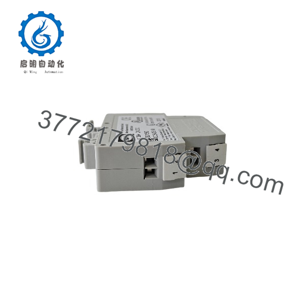
H4135A 992413560
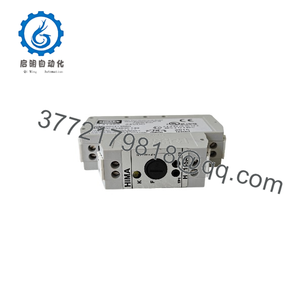
H4135A 992413560
Replacement & Installation Procedure
1.Power Isolation & Safety Checks:Locate circuit feed and apply Lock-Out/Tag-Out (LOTO).
De-energize the 24 VDC control circuit and field contact lines connected to the target H4135A relay. Verify zero potential across terminal blocks using a calibrated multimeter.
2.Wiring Disconnection:Label conductor numbers and detach screw terminals.
Label each wire corresponding to its relay terminal number. Carefully unscrew and pull out field and coil wiring from the IP20 screw terminals.
3.Physical Module Replacement:Release DIN rail mounting latch and swap relay body.
Insert a flat-head screwdriver into the bottom orange DIN rail retention clip, pull downward, and unhook the legacy H4135A module from the 35 mm rail. Snap the new unit firmly onto the rail.
4.Wiring & Loop Verification:Reconnect conductors, restore 24 VDC, and test loop.
Reinsert wires into screw terminals according to circuit schematics and torque securely. Reapply 24 VDC power and verify the front status LED lights up during test coil actuation.
Frequently Asked Questions (FAQ)
Q: What is the primary purpose of the HIMA H4135A safety relay?
A: It provides galvanically isolated, fail-safe signal coupling between HIMA safety PLC outputs (or control loops) and field equipment like trip valves, alarm annunciators, or interlock contactors.
Q: Can the be installed in hazardous process areas?
A: Yes. The (P/N 992413560) is rated for Class I, Division 2 and ATEX Zone 2 (II 3 G Ex nC IIC T4 X) environments when mounted in an appropriately rated protective enclosure.
Q: Is the HIMA repairable down to the component level?
A: No. Safety relays are sealed, single-piece modular components. If internal contacts fail or degrade, the complete module must be replaced to maintain functional safety certifications.



