
 WhatsApp: +86 16626708626
 Email:
  Phone: +86 16626708626
Description
Key Technical Specifications
| Parameter | Value |
| Part Number | LYD105A |
| Manufacturer | Hitachi |
| Number of Outputs | 32 points per module |
| Isolation Method | Mechanical/Optical isolation network |
| Rated Output Voltage | 12 to 24 V DC |
| Maximum Load Current | 0.5 A per point (Depending on thermal configuration) |
| Response Time (OFF → ON) | 1 ms or less |
| Response Time (ON → OFF) | 1 ms or less |
| Internal Current Dissipation | 200 mA or less (at 5 V DC backplane power) |
| External Wiring Connection | High-density detachable terminal block |
| Status Indication | Logic-side green LED indicators per output channel |
| Dielectric Strength | 1,500 V AC for 1 minute (all terminals to ground) |
Product Introduction & Supply Chain Strategy
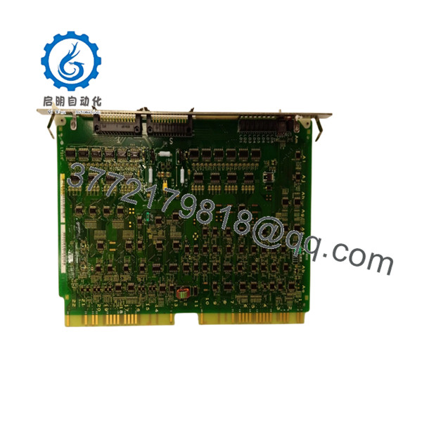
The Hitachi LYD105A is a high-density 32-point digital output module engineered for the legacy H-Series programmable logic controller environment. This module acts as the physical command bridge between the PLC’s central processor and external field equipment, driving discrete devices such as solenoid valves, motor starter coils, indicator pilot lights, and interposing relays. By executing sub-millisecond switching sequences, it provides reliable, real-time control over critical factory automation loops and process cell machinery.
Procuring this component as a New Surplus unit is a critical step for optimizing the Total Cost of Ownership (TCO) across aging production facilities. Because the Hitachi H-Series platform has achieved legacy status, procuring replacement parts direct from factory manufacturing runs is hit with massive lead times and high cost premiums. Transitioning to an unused, verified New Surplus unit allows procurement teams to secure original OEM performance immediately. This avoids the distinct failure risks associated with refurbished cards, such as degraded switching contacts or weakened internal traces, and gives your maintenance crews the parts availability they need to instantly wipe out unplanned plant downtime risks.

- LYD105A
- LYD105A
Installation & Configuration Guide
Stage 1: Pre-Installation (Prep & Safety)
- Execute full lock-out/tag-out (LOTO) procedures on the primary power supply supplying the PLC chassis rack and the external field voltage loops. Use a calibrated voltage meter to ensure all power rails inside the enclosure are dead.
- Fasten a grounded anti-static wrist strap tightly around your wrist, clipping the other end to an unpainted grounded steel frame component of the control cabinet enclosure.
- Take high-resolution reference digital photos of the existing wiring setup, terminal block alignments, and the hardware revision codes on the side of the original LYD105A card.
Stage 2: Removal
- Loosen the retention screws on the high-density external terminal block and gently pull the entire wiring cluster away from the module face.
- Back out the top and bottom chassis locking fasteners that secure the LYD105A module inside the backplane track.
- Grip the module securely by the upper and lower edge moldings and pull it straight out of the slot guide rails to prevent twisting or stressing the rear pin headers. Put the old board directly inside an ESD-shielded storage bag.
Stage 3: Installation (Clone & Seat)
- Unbox the New Surplus Hitachi LYD105A card within your clean, static-protected service workspace.
- Check that the configuration layout and terminal pinout options on the new unit replicate the layout configurations recorded in your pre-installation photographs.
- Line up the card edges with the clear plastic slots in the PLC rack. Slide the module backward smoothly until the backplane connector locks firmly into the rear data bus.
- Tighten the chassis locking fasteners down to secure the physical card assembly.
- Re-seat the external terminal block connector and secure its alignment fasteners to the face of the card.
Stage 4: Power-On & Testing
- Confirm all tools are removed from the rack workspace, unclip the ESD wrist strap, and close the enclosure doors.
- Disengage your LOTO devices and restore the main supply voltage to the PLC rack system and external actuator power circuits.
- Monitor the front status lights on the LYD105A card. The primary green power indicator must turn on solid, and individual channel indicators must reflect the true execution commands of the application program.
- Bring up your system workstation terminal to verify that the PLC CPU detects the LYD105A module address cleanly, showing zero network packet errors or communication drop faults on the rack bus.
Firmware/Software Versions & Upgrade Notes
The LYD105A digital output board is engineered for drop-in hardware replacement and requires no specialized software firmware loads in the field. Addressing and channel mapping are determined automatically by the slot position on the H-Series backplane, meaning it mirrors the configuration of the legacy module to prevent immediate rack addressing errors.
Ensure that your master PLC application program is configured to match the 32-point output data map required by this specific hardware variation. Mixing output configurations within the software structure without matching physical hardware adjustments can lead to data truncation or register mismatch faults. Never change system bus configurations while the processing rack is actively running, as the resulting communication break can cause the main controller to crash.
Frequently Asked Questions (FAQ)
Q: Are these LYD105A modules actually new, and how do they differ from refurbished inventory?
A: Yes, this unit is guaranteed to be New Surplus stock. It is a genuine Hitachi assembly that has spent its entire lifespan stored in a climate-controlled warehouse in original anti-static packaging. It has never seen active duty on a factory floor and contains no repaired circuits, board-level jumper patches, or swapped components. Refurbished boards are failed cards that have been manually repaired, which often leaves old, thermal-stressed components vulnerable to early failure.
Q: Why does the purchase price run higher than repaired items but below factory list cost?
A: The price reflects the exact market value of securing unblemished, immediately available, and authentic spare parts for legacy systems that are no longer actively produced by the OEM. Refurbished cards are cheap because they pose a massive operational gamble. This New Surplus module gives your engineering team 100% operational confidence and an original factory lifecycle without the extreme cost markups or production delays of factory special-orders.
Q: Can this digital output module be hot-swapped while the PLC rack is powered up and running?
A: No, this module does not support hot-swapping. Extracting or inserting the LYD105A module while the backplane power rail is energized will cause electrical arc transients across the signal pins. This can instantly destroy the delicate onboard switching components, fry the output channels, and propagate data faults across adjacent cards on the shared backplane bus.
Q: Does the 32-channel setup require an external power supply to drive the output loads?
A: Yes. The internal PLC backplane power only runs the logic-side circuitry and status LEDs of the LYD105A module. You must route an external 12 to 24 V DC power loop through the terminal block connections to supply the necessary voltage and current for driving your physical field actuators and relays.
Q: What type of warranty protection covers this New Surplus Hitachi component?
A: We provide a solid 1-year commercial replacement warranty on this LYD105A module, starting from the date of shipment. Because every single piece of hardware passes through physical QA inspections and is managed under strict ESD guidelines, we guarantee it will slot directly into your legacy rack system and operate identically to a factory-direct part.


