
 WhatsApp: +86 16626708626
 Email:
  Phone: +86 16626708626
Description
Key Technical Specifications
| Parameter | Value |
|---|---|
| Manufacturer | Honeywell |
| Model | MC-TAMR03 |
| Part Number | 51309218-175 |
| Product Type | LLMux RTD Field Termination Assembly |
| I/O Function | Low-Level Analog Input, RTD |
| Number of Channels | 16 |
| FTA Type | LLMux RTD |
| Terminal Type | Compression |
| Mounting Size | B |
| System Family | Honeywell TDC 3000 / Process Manager I/O |
| Application | RTD temperature signal termination |
| Coating | Conformally coated |
| CE-Compliant Part Number | 51309218-175 |
| Related Hardware | Honeywell C200 / Process Manager I/O |
| Compatibility Check | Verify installed system revision and associated I/O hardware |
The Honeywell hardware planning table distinguishes the MC-TAMR03 from the similar MC-TAMR02. MC-TAMR03 uses 51309218-175, while MC-TAMR02 uses 51304477-150; both are 16-channel LLMux RTD FTAs, but they are different part numbers and should not be substituted without documentation approval.
Product Introduction
The Honeywell MC-TAMR03, part number 51309218-175, is a 16-channel low-level analog RTD Field Termination Assembly used with Honeywell Process Manager/TDC 3000 I/O hardware. It provides compression-terminal termination for RTD field signals and is identified as a Mounting Size B LLMux RTD FTA.
For replacement work, the important checks are the complete part number, FTA type, channel count, terminal arrangement, and installed Honeywell I/O architecture. Do not substitute the similar MC-TAMR02 51304477-150 solely because both are 16-channel RTD FTAs.
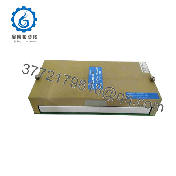
51309218-175
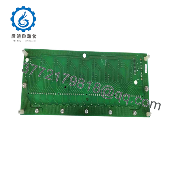
51309218-175
Installation & Configuration Guide
Stage 1: Pre-Installation Preparation — Approximately 10 Minutes
⚠️ Safety First: Notify operations and place the affected temperature measurement loops in the approved safe state. Follow the plant’s lockout/tagout procedure before disconnecting field wiring. Do not remove the FTA while energized unless the specific Honeywell installation documentation explicitly permits that procedure.
Tools Required:
- ESD wrist strap
- PH1 screwdriver or the appropriate terminal-tooling for the installed assembly
- Calibrated digital multimeter
- Wire labels
- Smartphone or camera for wiring photographs
- Approved Honeywell wiring drawings
- Current I/O configuration documentation
Data Backup:
- Record MC-TAMR03 / 51309218-175 from the existing nameplate.
- Photograph the complete FTA before disturbing any wiring.
- Photograph every terminal group and wire label.
- Record the associated I/O processor and carrier location.
- Record the affected RTD channel numbers.
- Verify whether the installed RTD circuits use 2-wire, 3-wire, or another site-specific termination arrangement from the approved drawings.
- Save the applicable controller/I/O configuration before maintenance.
⚠️ Do not identify this unit only as a generic “analog input module.” Honeywell documentation specifically classifies 51309218-175 as an LLMux RTD FTA.
Stage 2: Removing the Old Module — Approximately 5 Minutes
- Confirm the affected I/O is in a safe maintenance state.
- Isolate power according to the approved Honeywell maintenance procedure.
- Remove the applicable enclosure or protective cover.
- Photograph the complete wiring arrangement again before disconnecting anything.
- Label wires that are not already clearly identified.
- Disconnect the field wiring carefully.
- Do not pull on RTD conductors or use excessive force on compression terminals.
- Release the applicable mounting hardware.
- Remove the FTA while supporting the assembly mechanically.
- Inspect the mounting surface, terminals, and associated cabling for corrosion, loose hardware, or damaged insulation.
Keep the old FTA available until commissioning is complete. It provides a physical reference if a field wire or terminal assignment is questioned during startup.
Stage 3: Installing the New Module — Approximately 5 Minutes
- Verify the replacement label reads MC-TAMR03 / 51309218-175.
- Confirm the replacement has the same terminal arrangement as the removed assembly.
- Confirm that the associated Honeywell I/O hardware is approved for the MC-.
- Put on the grounded ESD wrist strap before handling the assembly.
- Position the FTA correctly on the mounting hardware.
- Secure the assembly without overtightening.
- Reconnect every RTD conductor according to the approved wiring diagram.
- Verify terminal numbers against the photographs taken before removal.
- Check shield and grounding connections according to the site wiring standard.
- Perform a point-by-point visual inspection before restoring power.
Self-Checklist:
- 51309218-175 verified
- MC- verified
- 16-channel configuration verified
- Compression terminals verified
- Mounting Size B arrangement verified
- RTD wiring matches drawings
- Shield/ground connections checked
- Mounting hardware secured
Stage 4: Power-On & Testing — Approximately 10–20 Minutes
- Perform a final wiring inspection before energizing the system.
- Check for accidental shorts or unintended continuity between relevant terminals.
- Restore power using the approved Honeywell startup procedure.
- Verify the associated I/O hardware returns to its expected operating state.
- Confirm that all 16 configured channels appear correctly in the system configuration where applicable.
- Compare several process values against local temperature references or an approved simulation source.
- Test representative RTD channels individually.
- Confirm that channel values change in the expected direction when the test condition changes.
- Check for open-circuit, short-circuit, or abnormal input indications.
- Return the loops to normal operation only after the affected channels pass the plant’s functional test.
⚠️ Do not invent electrical specifications for the RTD sensor simply from the FTA part number. Sensor type, wiring arrangement, excitation, scaling, and alarm configuration depend on the associated Honeywell I/O architecture and configured application.
For a replacement acceptance test, document the part number, hardware revision, channel test results, measured values, I/O status, and technician/date information. A test report is preferable to relying only on a visual inspection.
Frequently Asked Questions (FAQ)
Q1. What is Honeywell 51309218-175?
Honeywell 51309218-175 is the part number for the , a 16-channel LLMux RTD Field Termination Assembly with compression terminals. Honeywell’s hardware planning documentation lists it as Mounting Size B.
Q2. Is 51309218-175 an RTD input card?
Not exactly. It is an RTD Field Termination Assembly (FTA) rather than a standalone generic analog input card. It provides the field termination interface for the associated Honeywell low-level multiplexed RTD I/O architecture. Calling it simply an “analog input card” can cause confusion when selecting the replacement.
Q3. Is 51309218-175 the same as 51304477-150?
No. Honeywell identifies 51304477-150 as MC-TAMR02 and 51309218-175 as MC-. Both are listed as 16-channel LLMux RTD FTAs with compression terminals, but they have different part numbers. Do not assume interchangeability without checking the installed system documentation.
Q4. Can I hot-swap the MC-?
Do not assume it is hot-swappable. The safe approach is to follow the specific Honeywell hardware documentation and your plant’s approved maintenance procedure. If the procedure does not explicitly authorize energized removal, isolate the affected hardware before removing the FTA.
Q5. Is Honeywell 51309218-175 obsolete?
It is legacy installed-base hardware, and secondary-market listings describe the part as discontinued. That does not mean an existing system must immediately be migrated. Plants commonly continue operating legacy Honeywell I/O while maintaining a controlled spare-parts strategy.
Q6. What condition should I specify when purchasing 51309218-175?
Specify the exact condition rather than accepting “available” as a condition description:
- Factory Sealed / New Original — unopened OEM packaging where documentation supports it.
- New Surplus — unused inventory that may have been stored outside the OEM supply chain.
- Refurbished / Tested — previously used hardware that has undergone documented testing.
Ask for photographs of the actual 51309218-175 nameplate, revision marking, terminal assembly, and packaging. Marketplace listings show that this part is offered in multiple conditions, including unused original packaging and refurbished units.
Q7. What should I verify before ordering?
Give the supplier the complete 51309218-175 part number, MC- model designation, installed Honeywell system family, FTA type, channel count, terminal arrangement, and hardware revision. Most importantly, compare the existing unit’s physical termination arrangement with the replacement.
Honeywell’s configuration table explicitly identifies MC- / 51309218-175 / 16 channels / compression terminals / Mounting Size B, making those details useful order-verification checkpoints.



