
 WhatsApp: +86 16626708626
 Email:
  Phone: +86 16626708626
Description
Key Technical Specifications
| Parameter | Value |
|---|---|
| Platform | Single-slot 1756 ControlLogix backplane, local or remote rack |
| PROFIBUS Role | DP Slave, PROFIBUS V0 Slave implementation |
| Baud Rate | Up to 12 Mbps |
| PROFIBUS Node Address | 0 to 125 |
| Input Data | 122 words maximum |
| I/O Data per Exchange | Up to 244 bytes Input and 244 bytes Output, 400 bytes total maximum |
| Data Mapping | User-configurable, mapped within the module’s InRAx data memory |
| Data Transfer Type | Ladder logic (module recognized as an Input/Output module with direct processor memory access) |
| Configuration Method | Configuration/Debug serial port (RS-232 cable included), config file edited on PC and downloaded to module |
| Backplane Current Load | 800 mA @ 5 Vdc |
| Shock | 30 g operational |
| Weight | 1.36 kg / 3.00 lbs |
⚠️ Operating temperature, storage temperature, and vibration ratings were not confirmed in this pass — pull the current MVI56-PDPS datasheet from ProSoft’s Legacy Products page before finalizing a spec sheet for a customer, since these figures can differ from the newer MVI56E-series enclosure.
Product Introduction
The MVI56-PDPS is a single-slot InRAx communication module from ProSoft Technology that lets a Rockwell Automation ControlLogix processor operate as a PROFIBUS DP slave device on a PROFIBUS DP Master network. It’s built around the PROFIBUS V0 Slave implementation, moving up to 244 bytes of input and output data per exchange (400 bytes total) through user-configurable data mapping in the module’s memory, with data transfer to the Logix processor handled entirely through ladder logic.
This is the legacy, non-Enhanced MVI56 platform — configuration runs through a serial Configuration/Debug port rather than Ethernet, and there’s no CF-card Personality Module for field-swap configuration transfer like the later MVI56E series. Where it still earns its place: plants running established PROFIBUS DP networks for power distribution, petrochemical, water/gas, and SCADA/DCS applications that don’t want to touch existing master-side configuration during a ControlLogix migration.
Installation & Configuration Guide
Stage 1: Pre-Installation Preparation (~10 min)
⚠️ Safety First: Notify operations of the downtime window, confirm the process is in a safe state, lock out/tag out chassis power, and wait 5 minutes for backplane capacitor discharge.
Tools Required: ESD wrist strap, PH1 screwdriver, digital multimeter, wire labels, smartphone for reference photos, RS-232 serial cable (typically included with the module).
Data Backup: Export the current ladder logic from RSLogix 5000 / Studio 5000. Document the PROFIBUS node address (0–125), the I/O data mapping table, and photograph any DIP switches or address rotary settings on the old module before removal.
Stage 2: Removing the Old Module (~5 min)
- Remove the front bezel/cover.
- Label the PROFIBUS bus cable and any I/O wiring before disconnecting.
- Release the rack locking tabs and pull the module straight out to avoid bending backplane pins.
- Inspect the backplane connector for bent pins or dust buildup.
⚠️ Keep the old module on hand until the replacement is confirmed communicating — the node address and data mapping settings are configured per-unit and easy to mismatch on a rebuild.
Stage 3: Installing the New Module (~15 min)
- ESD prep. Confirm the replacement is genuinely MVI56-PDPS — the MVI56E-series, MVI69-PDPS, and ILX56-PBS are related but not drop-in electrically or in configuration workflow.
- Configuration clone (critical): Set the PROFIBUS node address to match the documented value from Stage 1. Rebuild the I/O data mapping table in the module configuration file exactly as it existed on the old unit.
- Seat the module in the rack — confirm the locking tab clicks and the module is fully engaged with the backplane connector.
- Reattach the PROFIBUS bus cable and any I/O wiring per your labels.
Self-Checklist: [ ] Node address matches [ ] Data mapping table rebuilt [ ] Wiring reattached per labels [ ] Locking tabs engaged
Stage 4: Power-On & Testing (~10 min)
Pre-Power Check: Multimeter check across the 5V backplane rail for shorts before re-energizing.
- Power up the rack only — leave the PROFIBUS master’s downstream process isolated until comms are confirmed.
- Observe module LED status indicators for boot and communication status.
- Connect via the Configuration/Debug serial port to verify node address and data mapping match your documentation.
- Download the backed-up ladder logic if this is a fresh module.
- Dry-run test I/O exchange with the PROFIBUS master before releasing the process to full operation.
⚠️ Troubleshooting Note: If the module fails to establish a slave connection, check the node address and baud rate against the master’s GSD-file configuration first — a mismatched node address is a far more common cause of failure on this platform than a defective module.
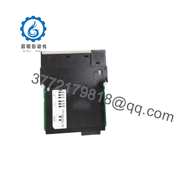
MVI56-PDPS
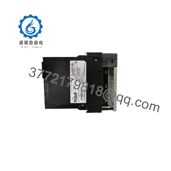
MVI56-PDPS
Frequently Asked Questions (FAQ)
Can the MVI56-PDPS be hot-swapped under power?
No. This is a backplane-powered module — pulling it live risks damaging the backplane connector pins on both the module and the chassis. Lock out chassis power and wait for capacitor discharge before removal.
Is the MVI56-PDPS obsolete, and is “new” stock genuinely new?
This is ProSoft’s original (non-Enhanced) PROFIBUS DP Slave platform, and it’s been in the field long enough that new-build factory stock is limited — most current supply runs through surplus/secondary channels. ProSoft’s newer ILX56-PBS platform is the direct current-generation replacement path. “New” surplus in this context means factory-sealed or pulled-but-unused units, not counterfeit boards — ask for serial number verification if that matters for your project documentation.
What’s the direct replacement if the -PDPS is out of stock or discontinued?
ProSoft’s ILX56-PBS PROFIBUS DPV1 Multi-Slave module can emulate the PROFIBUS DP identification numb the , which lets you replace the legacy module without reprogramming the PROFIBUS master device — though ProSoft’s own documentation notes this still requires ladder logic changes on the ControlLogix side, so budget time for that even on a “compatible” swap.
Will I lose my ladder logic when I pull the old CPU-side module?
Your ladder logic lives in the ControlLogix processor, n the , so a module swap alone doesn’t touch it. What you can lose is the module’s own configuration — PROFIBUS node address and I/O data mapping table — since this platform has no CF-card configuration transfer like the later MVI56E series. Document those settings from the old module before you pull it.
How is this different from the MVI56E-PDPS or newer Enhanced modules?
The nonnced uses a serial Configuration/Debug port and has no Ethernet-based diagnostics or CF-card Personality Module. If your application needs remote diagnostics over Ethernet or field-swap configuration via CF card, you’re looking at a different product line — don’t assume Enhanced-series features apply here.
Why is your price lower than new OEM factory pricing?
Surplus-channel sourcing carries less overhead than a new factory build, particularly on a legacy platform where new-build runs are limited — that’s where the margin difference comes from, not from a lesser unit. State plainly whether the unit quoted is factory-sealed new surplus or refurbished-and-tested, with serial number and functional test report available on request.



