
 WhatsApp: +86 16626708626
 Email:
  Phone: +86 16626708626
Description
3. Key Technical Specifications
| Parameter | Value |
|---|---|
| Part Number | H1127-0101 / 000068308 Rev 2.2 |
| Supply Voltage | 24 V DC (typical industrial control) |
| Power Consumption | Approximately 5–10 W (configuration dependent) |
| I/O Type | Mixed analog and digital signal processing |
| Communication | Proprietary backplane or serial interface (system-specific) |
| Firmware / Revision | Rev 2.2 |
| Mounting | Rack-mounted / card-slot insertion |
| Operating Temperature | −20 to +60 °C (typical control-cabinet range) |
| Storage Temperature | −40 to +85 °C |
| Application Domain | Turbine and marine automation systems |
4. Product Introduction
The Rolls-Royce H1127-0101 (PCB reference 000068308 Rev 2.2) is an OEM industrial control board used for signal processing and interfacing within proprietary turbine or marine control racks. It handles mixed analog and digital I/O under embedded firmware control and communicates via the system backplane.
This module is designed for continuous operation in industrial control cabinets serving gas or steam turbine packages and related marine propulsion systems. Exact pinout, channel assignments, and firmware behavior are system-specific; always verify compatibility against the original equipment documentation before installation.
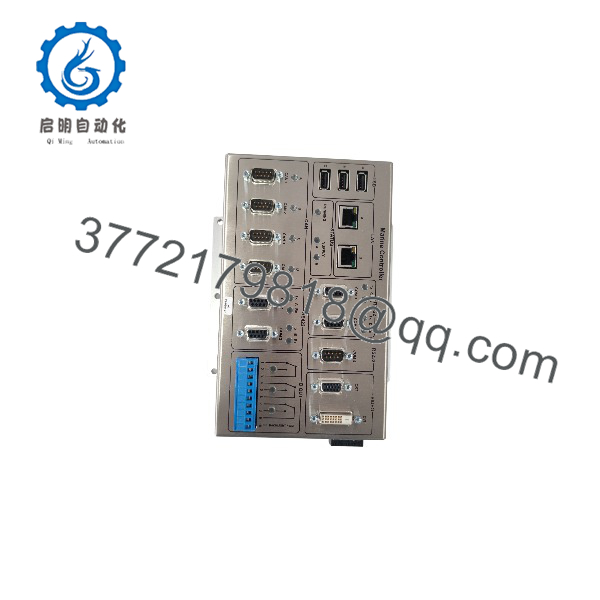
H1127-0101
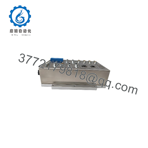
H1127-0101
5. Troubleshooting Quick Reference
| Symptom | Possible Cause | Relevance to this Part | Quick Check Method | Recommendation |
|---|---|---|---|---|
| Module not recognized by system | Poor backplane contact or wrong slot | ✅ High | Reseat board firmly; verify correct rack position and keying | Clean edge connector; confirm slot assignment per system manual |
| No power indication | Missing 24 V DC supply or blown fuse | ✅ High | Measure 24 V DC at backplane power pins | Restore supply; check upstream fusing and wiring |
| Intermittent signals or faults | Firmware mismatch or corrupted local data | ✅ Medium | Compare installed Rev 2.2 marking with system configuration | Reload or replace with matching revision; back up any local parameters first |
| Overheating | Inadequate cabinet cooling or overloaded channels | ✅ Medium | Measure board surface temperature and cabinet ambient | Improve airflow; verify channel loading against design limits |
| Communication loss with controller | Backplane bus fault or connector damage | ✅ High | Inspect edge connector for bent pins or contamination | Clean or replace connector; test with known-good board if available |
If the fault persists after these checks, provide the exact system type, rack position, measured supply voltage, and clear photos of the board markings to technical support.
6. Frequently Asked Questions (FAQ)
Q: Is the H1127-0101 still in current production?
A: This is an OEM-specific Rolls-Royce control board. Availability is limited to remaining new-surplus stock or certified refurbished units. Confirm the exact revision (Rev 2.2) and system compatibility before ordering.
Q: Can this board be used in any Rolls-Royce turbine control system?
A: No. Pinout, firmware, and I/O mapping are system-specific. Always cross-reference the original equipment list and rack documentation. Installing an incompatible revision can cause control faults.
Q: Does the board store application logic or only interface data?
A: Most Rolls-Royce architectures keep primary control logic in the central controller. Local calibration, addressing, or configuration data may reside on the board. Back up any non-volatile data before removal or replacement.
Q: What supply voltage does it require?
A: Typical industrial control supply is 24 V DC. Exact current draw and voltage tolerance depend on the installed configuration. Measure the actual backplane voltage before insertion.
Q: Why is secondary-market pricing often lower than OEM list?
A: These boards are frequently available as new surplus from decommissioned turbine packages or marine systems. Verified units remain functional, but they typically carry a seller warranty rather than a current Rolls-Royce factory warranty.
Q: Is special programming or configuration required after installation?
A: In many cases the board is recognized automatically once seated in the correct slot. Some systems require address or calibration parameters to be restored. Follow the specific system commissioning procedure.
Q: What should I check before replacing the board?
A: Record the exact part number and revision marked on the PCB, note the rack slot, photograph the edge-connector orientation, and confirm the system is powered down and locked out.



