
 WhatsApp: +86 16626708626
 Email:
  Phone: +86 16626708626
Description
Key Technical Specifications
| Parameter | A413015 Specification |
|---|---|
| Manufacturer | Valmet Automation / Metso Automation |
| Part number | A413015 |
| Board designation | NCU 09 |
| Product type | Network Control Unit circuit board |
| Primary function | NCU/system control and network interface functions |
| System family | Valmet/Metso Automation legacy control systems |
| Board format | Plug-in industrial control PCB |
| Revision | Revision-specific; examples of Ver.07 are commercially listed |
| Processor/memory specification | Not reliably established from publicly available primary documentation |
| Field I/O | Not established as a direct I/O module |
| Communication interfaces | System-dependent; exact interface configuration should be verified from the installed system |
| Replacement status | Legacy/discontinued; surplus, refurbished, and repair sources exist |
| Weight/dimensions | Verify against the physical board and OEM documentation |
Important specification note: Public documentation for A413015 is considerably less complete than documentation for newer Valmet automation hardware. Available sources establish the NCU 09 identity, but they do not provide a reliable OEM datasheet for voltage rails, processor type, memory capacity, connector pinout, or communication protocol. Those values should therefore not be inferred from similarly numbered A4130xx boards.
Product Introduction
The Valmet Automation A413015 is a legacy NCU 09 Network Control Unit circuit board used in Valmet/Metso Automation control equipment. Current aftermarket references consistently classify A413015 as an NCU board or PCB rather than an analog/digital I/O module.
This distinction matters during replacement. A413015 should be matched by the complete part number, board revision, installed system, firmware/software environment, and connector arrangement. Commercial listings also show revision-specific examples such as , indicating that revision should be checked rather than assuming every board is interchangeable.
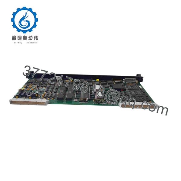
A413015
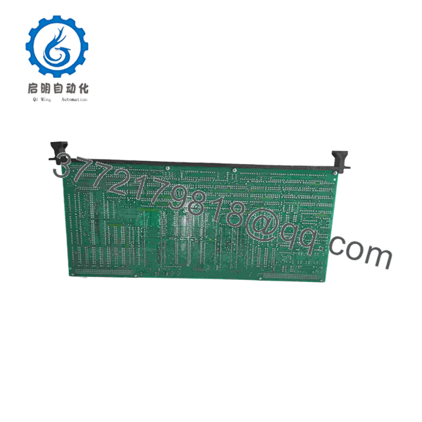
A413015
Installation & Configuration Guide
Stage 1 — Pre-Installation Preparation
Before replacing an :
- Place the associated automation system in the approved maintenance state.
- Follow the plant LOTO procedure.
- Allow at least 5 minutes for stored electrical energy to discharge, unless the OEM/site procedure specifies a longer period.
- Record the existing board’s:
- Complete part number
- Revision number
- Serial number
- Board labels
- Connector locations
- Installed rack/slot position
- Photograph all cable and backplane connections.
- Back up the controller/system configuration if the associated engineering environment permits it.
- Confirm that the replacement is specifically , not another A4130xx NCU, CPU, or communications board.
Because public technical information for this legacy board is limited, the existing board and system documentation are particularly important sources of configuration information.
Stage 2 — Removing the Existing Board
- Confirm that the system is fully de-energized.
- Remove the enclosure or rack access cover according to the system procedure.
- Identify the installation position.
- Label each removable cable before disconnecting it.
- Release the board retention mechanism.
- Withdraw the board vertically and evenly from the backplane.
- Inspect the backplane connector for bent pins, oxidation, contamination, or heat damage.
- Retain the original board until the replacement has been fully tested.
Do not force a board that does not release normally. Mechanical resistance can indicate an incorrectly positioned retaining mechanism or a damaged connector.
Stage 3 — Installing the Replacement
- Use ESD protection when handling the PCB.
- Confirm the replacement part number and revision.
- Compare connector positions and board markings against the removed board.
- Verify the rack/slot assignment.
- Insert the board into the correct backplane connector.
- Ensure that the PCB is fully seated before tightening the retaining hardware.
- Reconnect cables according to the photographs and wiring records.
- Check that no connector has been shifted by one position.
- Inspect the board for loose components, damaged connectors, contamination, or corrosion before energizing.
Do not copy jumper or switch settings blindly. Only reproduce them when the replacement board and its documentation confirm that the corresponding settings exist and perform the same function.
Stage 4 — Power-On & Testing
After installation:
- Verify supply wiring before energization.
- Power the system according to the approved startup sequence.
- Check board LEDs and system diagnostics.
- Confirm that the NCU is recognized by the host system.
- Check controller/network communication.
- Verify that the associated application software reports the expected NCU status.
- Confirm communication with connected system nodes.
- Review diagnostic/event logs for new faults.
- Perform an operational test before returning the process to normal service.
For a legacy NCU replacement, communication verification is more important than simply confirming that the board powers up. A board can pass a basic power-on check while still having a revision, firmware, configuration, or communication incompatibility.
Frequently Asked Questions (FAQ)
1. What is Valmet ?
is identified as a Valmet/Metso Automation NCU 09 circuit board, used as a Network Control Unit board in legacy automation systems.
2. Is an I/O module?
It should not be treated as a conventional analog or digital I/O module. Available listings consistently identify it as an NCU/control PCB.
3. Is still manufactured?
Available aftermarket sources identify the as discontinued. Current procurement is therefore commonly handled through surplus inventory, refurbished units, or repair services.
4. Are different revisions interchangeable?
Not automatically. Commercial listings specifically show revision-qualified units, including . The revision should be compared with the installed board and system documentation before substitution.
5. Can be replaced by another Valmet A4130xx board?
Do not assume so. Other A4130xx products are identified as different hardware, including CPU and other NCU-related boards. should be replaced only after confirming system compatibility, connector arrangement, revision, firmware, and configuration.
6. What should be checked when purchasing a replacement ?
At minimum, verify:
- Exact part number
- Board revision
- Physical board condition
- Connector condition
- System/rack compatibility
- Firmware or configuration compatibility
- Serial-number traceability
- Functional test availability
- Warranty or repair coverage
For obsolete control boards, “powers on” is not an adequate acceptance criterion. A proper replacement should be checked for communication, system recognition, diagnostics, and application-level operation.
7. Can a refurbished be used for a production system?
Potentially, but the acceptance criteria should be defined before purchase. A refurbished board should ideally undergo visual inspection, connector inspection, power-rail testing, communication testing, configuration verification, and application-level functional testing. The seller should provide actual test evidence rather than simply labeling the board “tested.”



