
 WhatsApp: +86 16626708626
 Email:
  Phone: +86 16626708626
Description
Key Technical Specifications
- Manufacturer: Yokogawa Electric Corporation, based on secondary-market identification
- Model Number: CP345
- Product Category: Industrial processor board module
- Primary Role: Processing board used within a compatible Yokogawa industrial control or embedded-system assembly
- Confirmed OEM Datasheet: Not located through publicly available sources
- Confirmed System Family: Not verified from an OEM source
- CPU Architecture: Not verified; do not rely on generic reseller claims of 32-bit, 2.4 GHz, or RISC processing
- Memory Capacity: Not verified; public listings contain conflicting unverified values
- Power Requirement: Not verified; do not assume 24 V DC from generic market listings
- Communications: Not verified; do not assume Ethernet, CAN, RS-232, RS-485, V-Net, or FIO compatibility without system documentation
- Form Factor: Not verified; inspect actual board size, edge connector, front panel, mounting, and rack/chassis interface
- I/O Capability: Not verified; CP345 should not be represented as a standalone I/O module without OEM evidence
- Redundancy Capability: Not verified; do not claim hot standby or bumpless transfer without the original system documentation
- Software Compatibility: Dependent on installed system firmware, board revision, application image, and host/controller environment
- Replacement Requirement: Match full board label, suffixes, revision, serial range, connector layout, PROM/flash modules, firmware, system rack/chassis, and original equipment documentation
- Procurement Requirement: Obtain clear photos of both sides, all labels, edge connectors, daughterboards, and installed equipment context before quoting compatibility
The only high-confidence public identification is that CP345 appears in secondary-market listings as a Yokogawa processor board/module. Search results also show a different Kontron CP345 legacy computer product, so the brand and physical board identity must be verified before treating any generic CP345 specification as applicable.
Product Introduction
Yokogawa CP345 appears to be a legacy industrial processor board used in a Yokogawa control or embedded-system assembly. It should be treated as a board-level replacement part, where connector compatibility, firmware, installed memory devices, daughterboards, and the host chassis matter as much as the basic model marking.
Public reseller descriptions for conflict sharply on system family, processor speed, memory, I/O, supply voltage, communications, and redundancy. Do not use those claims for engineering or procurement. Match the physical board and full label to the removed unit before ordering.
Troubleshooting Quick Reference
| Symptom | Possible Cause | Relevance to This Part | Quick Check Method | Recommendation |
|---|---|---|---|---|
| System does not boot or remains at startup | Missing chassis power, failed power supply, backplane fault, corrupted firmware, loose seating, board failure | ✅ High | Measure the chassis supply rails at the backplane using the equipment schematic; inspect status LEDs or console output; reseat the board with power removed | Verify all supply rails and backplane condition before replacing . |
| Board is not recognized by the host system | Incorrect slot, loose edge connector, incompatible revision, damaged backplane contact, firmware mismatch | ✅ High | Power down; inspect board guides, edge connector, keying, and host diagnostics; compare label/revision with the original board | Confirm the exact board revision and intended slot before ordering or installing a replacement. |
| System boots but application does not run | Missing application image, corrupted firmware, failed storage device, configuration mismatch, host communications failure | ✅ High | Capture startup messages, diagnostic codes, and system logs; verify that configuration media, PROMs, flash devices, or software licenses are present | Back up the original board and system image before replacement. Do not assume a spare contains the required application. |
| Intermittent resets or communication loss | Low supply voltage, ripple, overheating, loose board, corroded contacts, failing capacitor, external network problem | ✅ Medium | Measure supply rails under load; inspect cabinet temperature and airflow; check connector retention and log reset events | Correct power, thermal, and connection issues first. Replace only if the fault follows the board in a controlled test. |
| One external interface stops working | Cable fault, port configuration issue, external device failure, damaged transceiver, board interface failure | ✅ Medium | Test with a known-good cable/device; inspect port pins; compare signals and settings to a known-good system | Verify external wiring and configuration before replacing the processor board. |
| Replacement board powers up but system behaves differently | Wrong hardware revision, different firmware, missing programmed memory, different daughterboard, incorrect configuration | ✅ High | Compare front/rear labels, chips, jumpers, installed memory, daughterboards, firmware identifiers, and configuration files | Stop commissioning. Restore the verified firmware/application image and match all field-configurable hardware. |
| Board becomes hot or has visible damage | Incorrect chassis voltage, shorted backplane, failed regulator, conductive contamination, failed component | ✅ High | De-energize the system; inspect for discoloration, odor, corrosion, bulging capacitors, and damaged traces; check supply rails against equipment documentation | Replace damaged hardware only after identifying the power or environmental root cause. |
| Fault occurs after board handling or reinstallation | ESD damage, bent connector contact, board not fully seated, jumper moved, cable installed on wrong header | ✅ High | Inspect all connectors and jumper positions; compare photos taken before removal; verify seating and retention hardware | Use ESD controls, restore original jumper settings, and confirm connector orientation before powering up. |
❗ Identification warning: is not enough to establish full compatibility. Public search results include both Yokogawa listings and an unrelated Kontron legacy computer product. Do not release a purchase order without clear photos of the exact manufacturer logo, complete label, board revision, connector layout, and installed-system context.
❗ Firmware warning: A processor board can power up while still being unusable in the target system. Firmware, boot PROMs, flash images, application data, board revision, and installed daughterboards may be site-specific. Document every removable component before pulling the old board.
❗ Jumper warning: Photograph DIP switches, jumpers, rotary selectors, and connector orientation before removal. It is the most common rookie mistake, and it happens constantly. A moved jumper can change boot source, memory configuration, bus address, communications mode, or watchdog behavior.
❗ Backplane warning: Never force a board into a rack or chassis. Misaligned edge connectors can bend contacts and damage the replacement board or the host backplane. With power removed, inspect guide rails, keying, connector alignment, and retaining screws.
❗ Power warning: Do not assume 24 V DC, 5 V DC, or any other rail based on generic online claims. Use the original equipment electrical drawing and measure the chassis supply at the relevant connector. Wrong supply voltage can destroy legacy board hardware immediately.
❗ ESD warning: Use a grounded wrist strap, ESD mat, and antistatic packaging. I have seen a technician fix an intermittent seating issue, then handle the board on a dry cardboard box and create a non-repeatable communications fault. ESD damage often leaves no visible mark.
Keep these checks in mind and you will save yourself 90% of typical rework time. If you need support, provide full front/rear photos, manufacturer logo, complete part label, board revision, rack/chassis model, power-rail readings, boot messages, diagnostic logs, firmware identifiers, and photos of all jumpers and daughterboards.
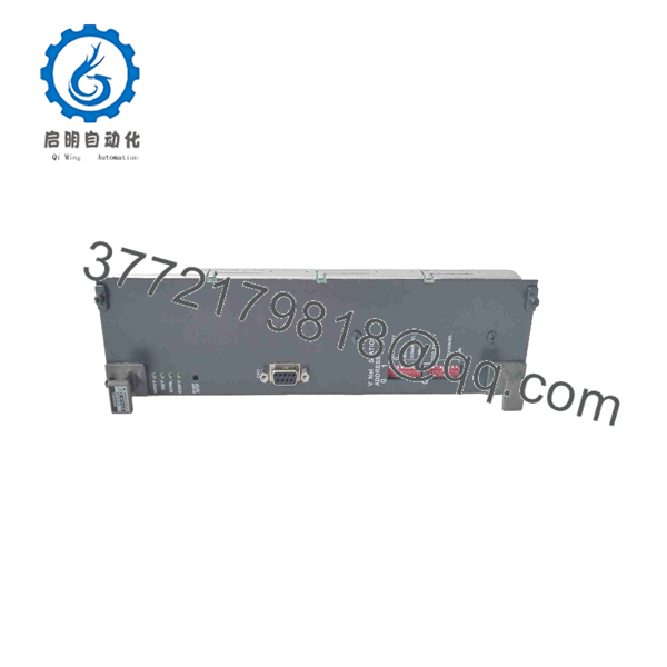
CP345
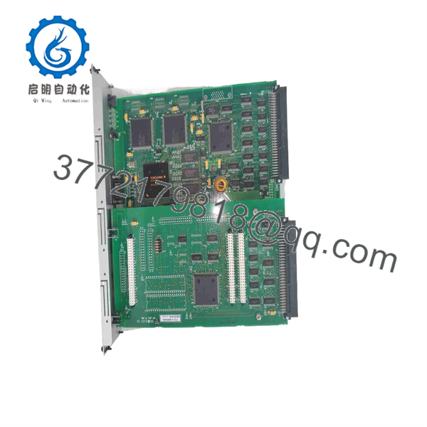
CP345
Frequently Asked Questions
What is the Yokogawa ?
is identified in secondary-market sources as a Yokogawa industrial processor board module. However, no authoritative public Yokogawa datasheet was located that confirms its processor architecture, memory, I/O, power requirement, communications, system family, or firmware compatibility.
Treat it as a legacy board-level replacement part until the exact equipment documentation and physical hardware are verified.
Is a Yokogawa CENTUM VP processor?
That has not been verified from an OEM source. Some reseller pages claim belongs to CENTUM VP or other Yokogawa DCS families, but the published details conflict with each other and should not be used as an engineering basis.
Confirm the actual control-system platform from the cabinet, rack, engineering workstation, system documentation, and original board label. A processor board from one Yokogawa product family is not automatically compatible with another.
Is the same as Kontron ?
No. Search results identify a separate Kontron product that is a legacy computer product and no longer actively supported. A Yokogawa listing and a Kontron product are unrelated unless your physical hardware proves otherwise.
Always verify the manufacturer logo. This is a good example of why part-number-only sourcing can cause a costly wrong shipment.
Can I replace with another board that looks similar?
No. Similar appearance does not prove compatible bus timing, power rails, firmware, pinout, boot devices, or chassis support. A wrong processor board can fail to boot, corrupt system configuration, damage the backplane, or leave the controlled process unavailable.
The minimum matching set is:
- Manufacturer and complete model label
- Board revision and serial range
- Front-panel connector arrangement
- Rear/edge connector style and keying
- Installed firmware, PROMs, flash devices, and memory modules
- Jumper and DIP-switch positions
- Host chassis, rack, or equipment model
- Application software and configuration backup
Can I hot-swap a processor board?
Do not hot-swap it unless the original equipment manufacturer explicitly documents the exact board and chassis as hot-swappable. A processor-board removal can halt the system, corrupt data, lose communications, interrupt process control, or damage the board/backplane.
To be honest, live processor-board replacement is not a shortcut. Schedule the work, archive configuration, place the process in a safe operating state, follow lockout/tagout and shutdown procedures, allow stored energy to discharge, and verify all connectors before restart.
Will a replacement retain the original application configuration?
Do not assume it will. A surplus board may be blank, contain an unknown program, have a different firmware revision, or lack the memory/option hardware used by the original system. The application may reside on the board, removable memory, a host computer, or a separate storage device depending on the system design.
Before removal, archive:
- Full board label, revision, serial number, and component markings
- Boot messages and firmware identifiers
- Configuration files and application backups
- Removable memory, PROM, or flash device locations
- Jumper and DIP-switch positions
- Chassis/rack position and all connector locations
- Network addresses, serial settings, and host communications mapping
- Process or machine startup and shutdown procedures
Why is a New Surplus cheaper than factory supply?
New Surplus units may come from unused project inventory, OEM warehouse spares, cancelled retrofits, system-integrator stock, distributor inventory, or decommissioned-system spares. Lower pricing often reflects the age of the platform and secondary-market sourcing.
For a New Original / New Surplus processor board, request:
- Clear photos of both sides and all labels
- Manufacturer logo and full part number
- Board revision, serial number, and date code where visible
- Photos of edge connectors, front-panel ports, jumpers, daughterboards, and installed ICs
- Confirmation whether firmware, PROMs, memory, or storage devices are included
- Clear condition statement: Factory Sealed, New Original / New Surplus, or Refurbished (tested)
- Warranty duration, return terms, verified quantity, and actual dispatch lead time
What testing should a supplier complete before shipping?
Because no authoritative public specification was located, testing must be based on the exact manufacturer, board revision, and host equipment. A credible supplier should document the limitation rather than invent specifications.
- Inbound inspection and traceability: Verify the manufacturer logo, complete label, board revision, serial number, source documentation, and component markings. Inspect for corrosion, altered labels, rework marks, scratched traces, missing ICs, bent pins, damaged connectors, capacitor leakage, heat discoloration, or cracked board material.
- Mechanical comparison: Compare the candidate board with the buyer’s photographs of the original. Verify dimensions, mounting points, connector positions, keying, front-panel cutouts, jumper locations, and installed daughterboards.
- Power-rail verification: Use a protected bench or compatible host chassis to apply only the verified supply rails specified by the original equipment documentation. Monitor current draw and temperature. Do not infer supply voltage from a generic online listing.
- Host boot test: Install the board in a known-compatible chassis or test rack. Verify that the host recognizes the board, completes startup diagnostics, and reports the expected firmware or boot state.
- Interface test: Test only documented interfaces using the correct cables and host equipment. Verify communication stability, device detection, and expected status behavior. Do not claim Ethernet, CAN, serial, fieldbus, or I/O functionality unless the exact board configuration supports it.
- Configuration and memory test: Record firmware identifiers, installed memory devices, jumper settings, and nonvolatile-memory retention. Clearly state whether the board ships blank, with unknown contents, or with a buyer-provided firmware image.
- Load and thermal observation: Where a compatible system is available, operate the board under representative application or communications load for more than 24 hours. Monitor resets, watchdog events, communication dropouts, temperatures, and supply stability.
- Final QC and packaging: Obtain QC sign-off, protect connectors with ESD-safe materials, package in an antistatic bag with foam protection, use heavy-duty corrugated boxing, and apply a dated QC-passed label. Test photos and the actual test report should be available upon request.



