WhatsApp: +86 16626708626
 Email:
 Phone: +86 16626708626
Description
Core Product Summary
The Yokogawa SAI143-H63 is an analog input module for the ProSafe-RS safety instrumented system, one of the SIL3-compliant I/O modules developed on the FIO hardware base for ProSafe-RS. The module acquires 16 isolated 4 to 20 mA current input signals from field instruments or valve positioners and installs in the ProSafe-RS Safety Node Unit or Safety Control Unit; it can be configured in a dual-redundant arrangement.
The order code identifies this variant precisely: -H specifies HART communication capability, the digit 6 specifies connection via a signal cable interface adapter (dedicated KS cable) without explosion protection, and the digit 3 specifies the ISA Standard G3 environmental rating with a −20 to +70 °C temperature range. With the HART function, the module passes HART digital communication from connected smart transmitters to Yokogawa’s Plant Resource Manager (PRM) for device configuration and diagnostics, without affecting the safety functions on the Safety Control Unit. Key performance data includes a 40 ms data update frequency, rated accuracy of ±16 µA (input range 0.05 to 23 mA), per-channel 2-wire/4-wire transmitter setting, and an integral transmitter power supply delivering 16.15 V minimum at 20 mA (26.4 V maximum at 0 mA, current limited to 25 mA). The module weighs approximately 0.39 kg with the signal cable interface adapter fitted.
Key Technical Specifications
| Parameter | Value |
|---|---|
| Product family / type | ProSafe-RS safety instrumented system (SIS) analog input module, FIO-based |
| Order code structure | SAI143-H63: -H HART communication; 6 = signal cable interface adapter (dedicated cable), no explosion protection; 3 = ISA Standard G3, −20 to +70 °C |
| Number of input channels | 16 channels, module isolation |
| Rated input range | 4 to 20 mA |
| Permissible input range | 0 to 25 mA |
| Rated accuracy (H type) | ±16 µA (input range 0.05 to 23 mA); ±32 µA for input below 0.05 mA (style code S3 or later) |
| Input impedance | Power-ON: 250 Ω plus protection-circuit voltage drop (module input impedance varies from 272.5 Ω at 20 mA to 362.5 Ω at 4 mA); Power-OFF: 500 kΩ minimum |
| Data update frequency | 40 ms |
| Temperature drift | ±16 µA per 10 °C |
| Transmitter power supply | 16.15 V minimum at 20 mA; 26.4 V maximum at 0 mA; output current limit 25 mA |
| 2-wire / 4-wire transmitter setting | Individual channel setting, changed by setting pins |
| Transmitter power ON/OFF function | Available in 2-wire setting, for all 16 channels simultaneously (supported by ProSafe-RS R4.03.00 or later and style code S4 or later) |
| Withstand voltage | 1.5 kV AC between input signal and system for 1 minute (500 V AC when a dedicated signal cable is used) |
| Maximum current consumption | 5 V system: 320 mA; 24 V system: 550 mA |
| HART communication | Available (-H); supports PRM management of HART devices |
| External connection (this variant) | Dedicated signal cable via signal cable interface adapter (pressure clamp terminal and MIL cable connection available on other suffix codes) |
| Redundancy | Module can be made dual redundant |
| Environmental rating | ISA Standard G3; ambient temperature −20 to +70 °C |
| Weight | Approx. 0.39 kg (with signal cable interface adapter) |
Engineering Selection Highlights
- Order-code digits are functional, not cosmetic — the “6” in -H63 selects the dedicated signal cable connection through an interface adapter; a plant wired with pressure clamp terminals or MIL cables needs the corresponding digit 5 variant instead. Matching the suffix to the existing marshalling style is the first selection decision.
- HART (-H) enables PRM-based device management — HART communication from smart transmitters is passed to the Plant Resource Manager without interfering with the safety functions on the Safety Control Unit; plants not using PRM or HART devices can use the -S standard type.
- Per-channel 2-wire/4-wire configuration by setting pins — loop-powered and externally powered transmitters can be mixed on one module, with the mode set physically per channel; plan the pin settings against the loop drawings during installation.
- Integral transmitter power supply is current-limited — the module supplies loop power at 16.15 V minimum under 20 mA load with a 25 mA current limit; verify each loop’s voltage budget against the module input impedance (272.5–362.5 Ω) and cable resistance.
- 40 ms data update with ±16 µA accuracy (0.05–23 mA) — the input range over which rated accuracy applies is documented explicitly; signals below 0.05 mA fall under a wider ±32 µA figure, which matters for broken-loop detection thresholds.
- Withstand voltage depends on the connection style — 1.5 kV AC applies to the standard connection, but only 500 V AC when the dedicated signal cable is used, which is exactly the connection style of the -H63; respect this limit in loop insulation testing.
- No Zener barriers — the module must not be connected with Zener barriers; intrinsic safety applications require an isolation barrier instead.
- G3 environment with a thermal channel restriction — the G3 rating covers −20 to +70 °C, and for related suffix codes the usable channel count is restricted above 60 °C ambient per the ProSafe-RS I/O module outline document; high-temperature cabinets should be checked against that restriction.
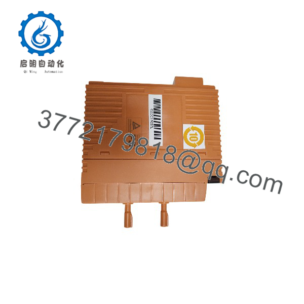
SAI143-H63
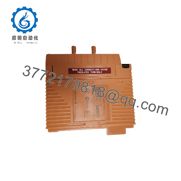
SAI143-H63
System Compatibility & Integration Requirements
| Item / Dependency | Verified Compatibility or Requirement | Practical Note |
|---|---|---|
| Host system | Yokogawa ProSafe-RS safety instrumented system | Module installs in the Safety Node Unit or Safety Control Unit |
| Mounting | FIO-based installation in the safety node unit; module can be made dual redundant | Redundancy is achieved by installing two modules; dual communication modules can be installed on the same unit |
| Field connection (this variant) | Dedicated signal cable (KS) via signal cable interface adapter | Alternative suffix codes support pressure clamp terminal or MIL connector cable connection |
| Input devices | 4 to 20 mA transmitters and valve positioners, 2-wire or 4-wire, set per channel | Loop budget must fit the module input impedance and supply limits |
| HART / device management | HART communication with -H; supported by Yokogawa Plant Resource Manager (PRM) | HART functions are interference-free with respect to the safety functions on the Safety Control Unit |
| Hazardous area practice | No Zener barriers; use an isolation barrier for intrinsic safety instrumented systems | Barrier selection must follow the ProSafe-RS documentation |
| Firmware dependency | Transmitter power ON/OFF function requires ProSafe-RS R4.03.00 or later and style code S4 or later | Used, for example, to reset alarm states of Fire and Gas devices in 2-wire settings |
| Environment | ISA Standard G3, −20 to +70 °C | Channel-count restrictions above 60 °C ambient apply to related suffix codes; consult the ProSafe-RS I/O modules outline document |
Dimensions, Mounting & Connection Notes
| Item | Data |
|---|---|
| Weight | Approx. 0.39 kg with signal cable interface adapter (approx. 0.34 kg for pressure clamp terminal block or MIL cable variants) |
| Connection (this variant) | Dedicated signal cable through the signal cable interface adapter |
| Alternative connections | Pressure clamp terminal block or MIL connector cable (other suffix codes); dual-redundant communication possible by installing two communication modules on the same unit |
| Channel configuration | 2-wire/4-wire transmitter mode set per channel via setting pins |
| Loop design values | Input impedance 272.5 Ω at 20 mA to 362.5 Ω at 4 mA (250 Ω plus protection-circuit drop, max. 0.45 V); transmitter supply 16.15 V min. at 20 mA, 26.4 V max. at 0 mA, current limit 25 mA |
| Insulation test limit | 1.5 kV AC between input signal and system for 1 minute; 500 V AC when the dedicated signal cable is used |
| Power consumption | 320 mA max. on the 5 V system, 550 mA max. on the 24 V system — budget these loads when planning node power supply |
| Environmental limits | ISA Standard G3; ambient −20 to +70 °C; restrictions on usable channel count above 60 °C apply to related suffix codes per the ProSafe-RS I/O modules outline |
Detailed Product Overview
The ProSafe-RS platform is Yokogawa’s safety instrumented system, and its I/O layer was engineered to SIL3 compliance on the basis of the company’s FIO hardware. The SAI143 is the current input member of that family: 16 channels of 4 to 20 mA acquisition with module-level isolation, a 40 ms data update frequency, and rated accuracy of ±16 µA across an input range of 0.05 to 23 mA. Within the family, the suffix codes define what a given unit can do, and the -H63 is a specific, not generic, configuration.
The letter distinguishes the HART variant: with -H, the module passes HART digital communication from connected smart devices to the Plant Resource Manager, enabling remote configuration, diagnostics, and device management from the PRM environment. Yokogawa documents this HART capability as interference-free with the safety functions on the Safety Control Unit — the device-management channel is logically separate from the safety path, which is the architectural property that makes HART support acceptable in a safety system at all. The two digits then define the physical and environmental build: the “6” specifies connection through a signal cable interface adapter for dedicated signal cabling (without explosion protection), and the “3” specifies the ISA G3 environmental rating covering −20 to +70 °C. A plant that uses pressure clamp terminals or MIL cables instead of dedicated cabling needs the corresponding digit-5 variant, and intrinsically safe installations require an isolation barrier since Zener barriers are explicitly excluded for this module.
Loop-level engineering centers on the module’s electrical footprint. The input presents 250 Ω plus the protection-circuit drop, varying between 272.5 Ω at 20 mA and 362.5 Ω at 4 mA, and the integral transmitter supply delivers 16.15 V minimum at full 20 mA load with a 25 mA current limit. Any 2-wire loop must therefore be budgeted across module impedance, cable resistance, and the transmitter’s own voltage requirement. Channel mode — 2-wire or 4-wire — is set physically with setting pins, per channel, so a mixed marshalling can be served by one module if the pin plan matches the loop drawings. For 2-wire loops, a documented transmitter power ON/OFF function can cycle loop power for all 16 channels simultaneously, which is used for example to reset latched alarm states of Fire and Gas devices; it requires ProSafe-RS R4.03.00 or later and style code S4 or later, so the plant’s system version matters when this function is part of the design intent.
Two boundary conditions deserve explicit attention in installation and test planning. First, the withstand voltage specification is 1.5 kV AC between input signal and system for one minute — but only 500 V AC when the dedicated signal cable is used, which is precisely the connection style of the -H63. Loop insulation testing above that level risks damaging the interface. Second, accuracy below 0.05 mA is specified at ±32 µA rather than ±16 µA; broken-wire detection thresholds set near live zero should account for the wider band.
The module draws up to 320 mA from the 5 V system and 550 mA from the 24 V system, figures that feed the node power budget. It weighs approximately 0.39 kg with the interface adapter fitted, can be arranged redundantly, and fits the same safety node units that host the rest of the ProSafe-RS SIL3 I/O family. For procurement, the practical verification points are the suffix digits against the installed cabling style, the style code where the newer functions are needed, and the ProSafe-RS system release that governs feature availability.
Applications & System Role
In a ProSafe-RS architecture, the SAI143-H63 is the safety-side analog acquisition point: it reads 4 to 20 mA signals from field devices — transmitters, valve positioners, and Fire and Gas detectors — and delivers the values to the safety logic in the Safety Control Unit, whose trip and alarm decisions depend on this data. The module is one of the SIL3-compliant I/O modules Yokogawa developed on the FIO hardware base specifically for ProSafe-RS, alongside the SAV144 voltage input, SDV144 digital input, and SDV531 digital output modules.
Fit scenarios that follow from the verified capability profile:
- Safety instrumented functions that require analog process values — pressure, temperature, level, or flow — as trip inputs in an emergency shutdown, fire and gas, or burner management context.
- HART-equipped smart transmitter plants that manage field devices through Yokogawa PRM, where the -H variant carries device configuration and diagnostic traffic alongside the analog signal without affecting the safety function.
- Safety node cabinets wired with dedicated KS signal cabling, where the interface adapter connection style of the -H63 matches the installed marshalling.
- Fire and gas applications using 2-wire detectors, where the transmitter power ON/OFF function (with the corresponding ProSafe-RS release and style code) supports alarm-state resets by cycling loop power.
- Redundant safety I/O designs, since the module can be installed in a dual-redundant arrangement within the safety node.
FAQ
What is the Yokogawa SAI143-H63?
It is a 16-channel, 4 to 20 mA analog input module for the ProSafe-RS safety instrumented system, with HART communication and a dedicated signal cable interface adapter connection.
What do the suffix codes mean?
-H specifies HART communication; the digit 6 specifies connection via a signal cable interface adapter (dedicated cable, no explosion protection); the digit 3 specifies the ISA Standard G3 environmental rating with a −20 to +70 °C temperature range.
Where is the module installed?
In the ProSafe-RS Safety Node Unit or Safety Control Unit, where it forms part of the SIL3-compliant FIO-based I/O layer; it can be installed in a dual-redundant arrangement.
What is its accuracy and update rate?
Rated accuracy is ±16 µA over an input range of 0.05 to 23 mA (±32 µA below 0.05 mA on style code S3 or later), with a 40 ms data update frequency and ±16 µA per 10 °C temperature drift.
Does it power 2-wire transmitters?
Yes. The integral transmitter supply delivers 16.15 V minimum at 20 mA, up to 26.4 V at 0 mA, with the output current limited to 25 mA; the 2-wire/4-wire mode is set per channel with setting pins.
What does the HART function provide?
It passes HART communication from smart field devices to the Plant Resource Manager (PRM) for device configuration and diagnostics, without affecting the safety functions on the Safety Control Unit.
Can the module be used in intrinsically safe loops?
Not with Zener barriers; Yokogawa requires an isolation barrier when the module is used in an intrinsic safety instrumented system.
What insulation test voltage applies?
1.5 kV AC between input signal and system for one minute generally, but only 500 V AC when the dedicated signal cable used by this variant is connected.